

3-D Airfoil CFD Simulation, ANSYS Fluent Training
Price: $12
This project presents a CFD simulation of airflow over an airfoil using ANSYS Fluent. The computational mesh was refined near the airfoil to capture boundary layer effects, and the k–ω SST turbulence model was applied for accurate prediction of lift and drag. The results highlight the pressure distribution, velocity field, and aerodynamic performance of the airfoil.
3-D Airfoil CFD Simulation
The focus of this research study lies in observing the action of aerodynamic flow around an airfoil by utilizing Computational Fluid Dynamics (CFD) in the ANSYS Fluent framework. Airfoils serve critical roles in both aircraft and turbine blades, where their aerodynamic effectiveness plays a dominant role in determining the properties of lift and drag. This study places its focus on pressure distribution, velocity fields, and wake patterns developed behind the airfoil for known flow conditions. CFD represents an efficient and accurate technique, allowing for modeling of flow dynamics virtually without requiring expensive experimental processes.
Project Description
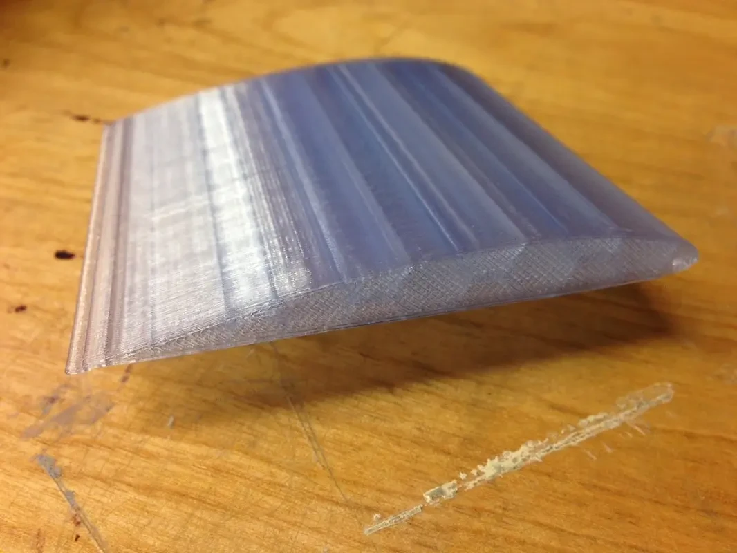
This project is going to study an incompressible isothermal air flow adjacent to a 3-D airfoil. The geometry is a 0.5-meter airfoil inside a wind tunnel. Also, the maximum speed of 10 m/s is selected for the inlet.
Geometry and Mesh
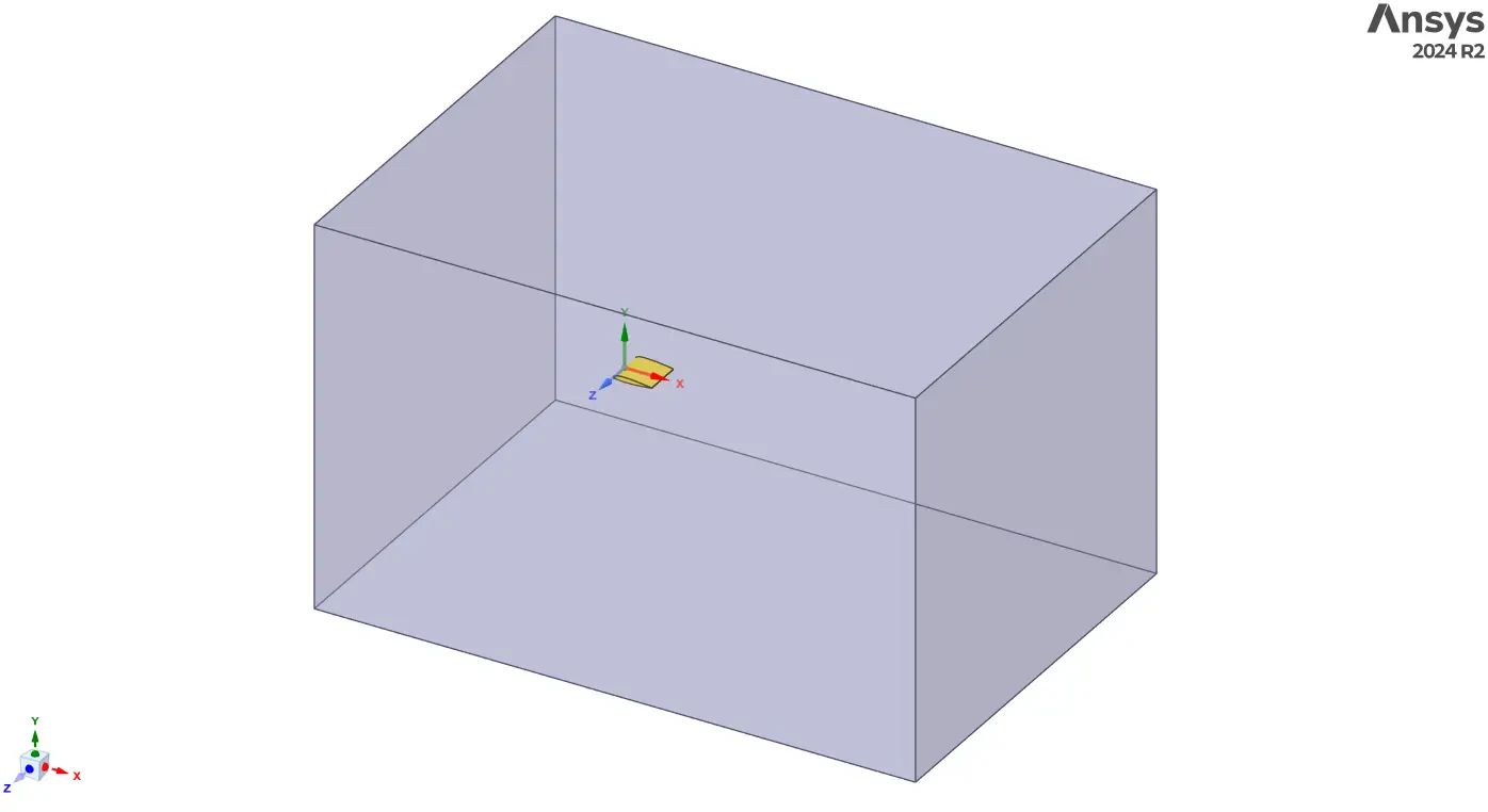
The geometry was created by placing a NACA-type airfoil profile at the center of a rectangular computational domain. The domain extends sufficiently far from the airfoil to avoid boundary effects on the region of interest. The inlet boundary represents the uniform free-stream flow, while the outlet acts as a pressure-outlet condition. The upper, lower, and side walls are treated as far-field or symmetry boundaries.
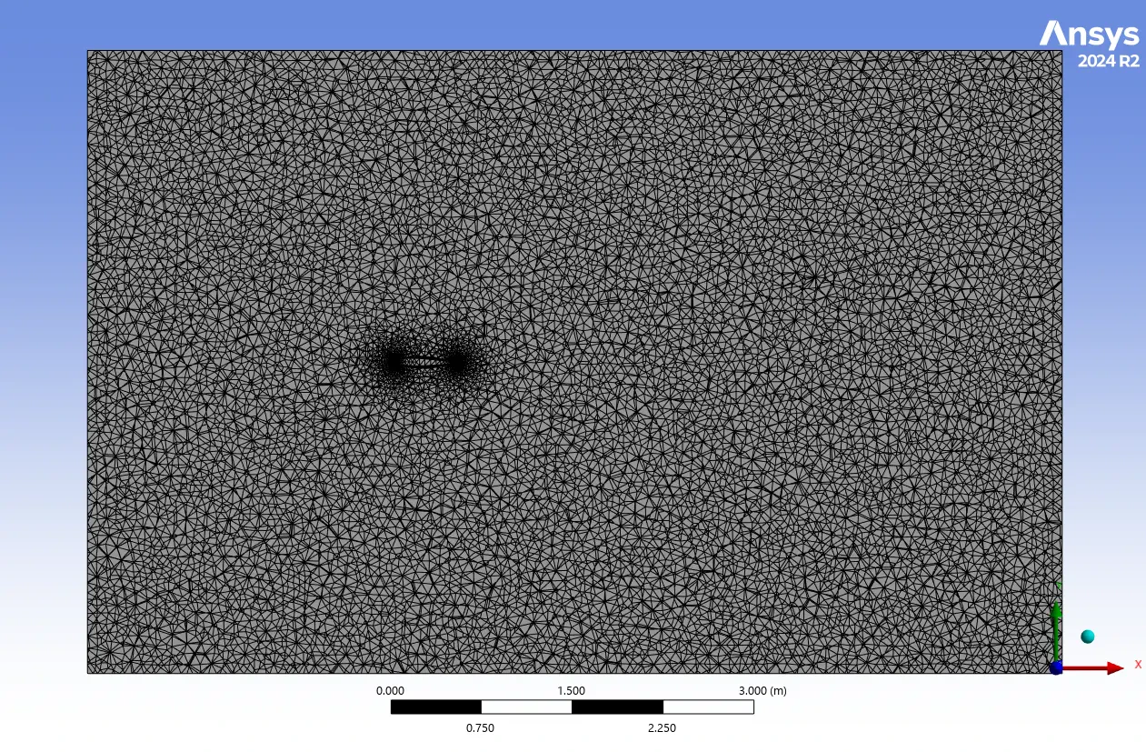
The mesh for the computational domain was generated using ANSYS Meshing. Unstructured triangular elements were employed with significant refinement in the vicinity of the airfoil. Fine mesh spacing around the leading edge, upper and lower surfaces, and trailing edge ensures accurate resolution of the boundary layer and wake region. The element size gradually increases toward the far-field boundaries, thereby reducing the total number of elements while maintaining accuracy in critical regions. The final mesh consists of approximately 380,000 nodes and over 2.1 million elements, providing a good compromise between computational cost and accuracy.
CFD Simulation Settings
The simulation was carried out in ANSYS Fluent using a pressure-based, steady-state solver. The working fluid was air with constant physical properties, including a density of 1.225 kg/m³ and viscosity of 0.001003 Pa·s.
- Boundary Conditions:
- Inlet: Velocity inlet = 10 m/s
- Outlet: Pressure outlet (atmospheric reference)
- Airfoil walls: No-slip condition
- Far-field boundaries: Symmetry
- Solver Properties:
- Pressure–velocity coupling: SIMPLE algorithm
- Pressure interpolation scheme: Second-order
- Momentum and turbulence equations: Second -order upwind
- Initialization: Standard initialization from the inlet
- Number of iterations: 1000 (default relaxation factors)
This setup ensures a stable convergence while capturing the velocity and pressure distributions over the airfoil with acceptable computational cost.
3-D Airfoil CFD Simulation Results and Discussions
The simulation results provide a detailed view of the pressure and velocity fields around the airfoil. The pressure contour demonstrates a high-pressure stagnation region at the leading edge, where the incoming flow directly impinges on the surface. On the upper surface of the airfoil, the pressure drops significantly as the flow accelerates, leading to a low-pressure region that is primarily responsible for generating lift. In contrast, the lower surface maintains relatively higher-pressure values, creating a clear pressure differential that results in a net upward aerodynamic force.
The velocity contour shows accelerated flow over the suction side (upper surface) and a velocity deficit that develops in the wake region at the trailing edge. The wake is characterized by vortical structures and energy loss, which contribute to aerodynamic drag. The k–ω SST turbulence model successfully captured the flow separation near the trailing edge under the given angle of attack, thereby predicting realistic lift and drag behavior.
Quantitative analysis of aerodynamic coefficients confirmed the increase in lift with flow acceleration over the upper surface as well as the contribution of viscous shear and wake formation to the overall drag. The mesh refinement near the airfoil surface played a crucial role in resolving the boundary layer accurately, which ensured reliable predictions of aerodynamic performance.