
Fluid-Structure Interaction (FSI) Course in ANSYS Fluent
Price:
$400
$279
Master the FSI process with our “Fluid-Structure Interaction (FSI): All Levels” CFD course using ANSYS Fluent. From basics to advanced, learn to perform procedures of FSI simulation by two approaches: System Coupling in ANSYS Workbench and Structure Model (Intrinsic FSI) in ANSYS Fluent. This course equips you with the essential skills to model the simultaneous interaction of fluid and solid in all engineering fields using CFD. Ideal for beginners and experts alike, enhance your capabilities in FSI analysis for cutting-edge research and industrial applications.
FSI Analysis of NACA 0014 Airfoil: Aerodynamic Forces and Structural Response
DescriptionIn this project, we present a simulation of an Airfoil exposed to the airflow via ANSYS Fluent software.Since the airfoil is exposed to airflow, an interaction occurs between the wind blowing and the airfoil structure. It means that airflow exerts a volume force on the airfoil's body by hitting it. Therefore, we intend to perform a numerical simulation of the airfoil as a Fluid-Structure Interaction (called FSI).The interaction between fluid and structure can be implemented as:One-way FSITwo-way FSIIn this project, we aim to analyze only the effect of fluid on the structure, and there is no need to account for the effect of the structure on the fluid. So, we choose One-way FSI, which is a simple and less-expensive approach.We modeled the geometry via SpaceClaim software. The computational domain is a sample space of the surrounding air that includes both fluid and solid domains. There is a solid airfoil structure within the fluid environment, which is considered fixed from the center.We meshed the computational domain via ANSYS Meshing software. The mesh is of an unstructured type, and approximately 1,700,000 cells have been generated.MethodologyFluid-structure interaction can be performed in two general methodologies:In the ANSYS Workbench environment, using an external solver (specifically, system coupling)Only in the Fluent solver (in the form of an intrinsic FSI).In this project, we implemented a one-way FSI in the ANSYS Fluent environment. In other words, the Fluent solver performs both fluid and solid calculations simultaneously.For two-way FSI in Fluent solver, the Structure model is utilized. The structural model can be implemented in two ways:Linear elasticity: The deformation is proportional to the applied force. In this case, the deformations are usually small, and the calculation process is faster.Nonlinear elasticity: The deformation is not necessarily proportional to the applied force. In this case, the deformations are usually large, and the calculation process is more complex and time-consuming.In this project, we considered fluid-structure interaction in the form of a Linear Elasticity state.Since we were analyzing one-way FSI and not considering the effect of structural displacement on the adjacent fluid, we didn't need to use the dynamic mesh model.ResultsWe analyzed the results in two fluid and solid approaches:In a fluid view, we studied the behavior of airflow. For this, we obtained the distributions of the pressure and velocity of air. The results show that the airflow collides with the airfoil body at high speed and, as a result, exerts a hydraulic force on the airfoil structure.In a solid view, we studied the behavior of the airfoil body under the influence of the applied forces of the air flow. For this, we obtained the distribution of the von Mises stress and displacements (in all directions). The results confirm that the airflow affects the airfoil structure and, as a result, it undergoes displacements relative to the fixed center.In conclusion, we can claim that we carried out the simulation project of an airfoil correctly and acceptably by using the two-way FSI method.
Fluid-Structure Interaction (FSI) Course in ANSYS Fluent
Price:
$400
$279
Master the FSI process with our “Fluid-Structure Interaction (FSI): All Levels” CFD course using ANSYS Fluent. From basics to advanced, learn to perform procedures of FSI simulation by two approaches: System Coupling in ANSYS Workbench and Structure Model (Intrinsic FSI) in ANSYS Fluent. This course equips you with the essential skills to model the simultaneous interaction of fluid and solid in all engineering fields using CFD. Ideal for beginners and experts alike, enhance your capabilities in FSI analysis for cutting-edge research and industrial applications.
-
Section 1
FSI Concepts: System Coupling
-
This chapter reviews the general concepts of fluid-structure interaction (FSI).It discusses the fluid computations in the Fluent solver and the solid computations in the Structural solver, and focuses on establishing data transfer between fluids and structures. As a suitable and common method, it introduces the system coupling tool for defining data transfer.In addition, it refers to one-way and two-way FSI to clarify their differences from an analytical perspective.
Lesson 1 3m 46s Free Lesson
-
-
Section 2
FSI Concepts: Intrinsic FSI
-
This chapter examines the detailed concepts of the intrinsic fluid-structure interaction (FSI).In order to reduce the computational cost, it is possible to eliminate the use of external solvers and perform simultaneous fluid and solid calculations with the Fluent solver alone. In this case, there is no need for data transfer and system coupling by the exterior solver. So, this is known as intrinsic FSI.This chapter describes the structure model in the Fluent solver. These computations can be performed in both linear elasticity and nonlinear elasticity modes.Then, it discusses the equations and relations related to the fluid and solid computations. These governing relations consist of applied forces (from the fluid), displacements (through the structure boundary), and ultimate deformations.In addition, it refers to one-way and two-way FSI to clarify their differences from an analytical perspective.
Lesson 1 11m 49s Free Lesson
-
-
Section 3
Airfoil: One-way FSI
-
DescriptionIn this project, we present a simulation of an Airfoil exposed to the airflow via ANSYS Fluent software.Since the airfoil is exposed to airflow, an interaction occurs between the wind blowing and the airfoil structure. It means that airflow exerts a volume force on the airfoil's body by hitting it. Therefore, we intend to perform a numerical simulation of the airfoil as a Fluid-Structure Interaction (called FSI).The interaction between fluid and structure can be implemented as:One-way FSITwo-way FSIIn this project, we aim to analyze only the effect of fluid on the structure, and there is no need to account for the effect of the structure on the fluid. So, we choose One-way FSI, which is a simple and less-expensive approach.We modeled the geometry via SpaceClaim software. The computational domain is a sample space of the surrounding air that includes both fluid and solid domains. There is a solid airfoil structure within the fluid environment, which is considered fixed from the center.We meshed the computational domain via ANSYS Meshing software. The mesh is of an unstructured type, and approximately 1,700,000 cells have been generated.MethodologyFluid-structure interaction can be performed in two general methodologies:In the ANSYS Workbench environment, using an external solver (specifically, system coupling)Only in the Fluent solver (in the form of an intrinsic FSI).In this project, we implemented a one-way FSI in the ANSYS Fluent environment. In other words, the Fluent solver performs both fluid and solid calculations simultaneously.For two-way FSI in Fluent solver, the Structure model is utilized. The structural model can be implemented in two ways:Linear elasticity: The deformation is proportional to the applied force. In this case, the deformations are usually small, and the calculation process is faster.Nonlinear elasticity: The deformation is not necessarily proportional to the applied force. In this case, the deformations are usually large, and the calculation process is more complex and time-consuming.In this project, we considered fluid-structure interaction in the form of a Linear Elasticity state.Since we were analyzing one-way FSI and not considering the effect of structural displacement on the adjacent fluid, we didn't need to use the dynamic mesh model.ResultsWe analyzed the results in two fluid and solid approaches:In a fluid view, we studied the behavior of airflow. For this, we obtained the distributions of the pressure and velocity of air. The results show that the airflow collides with the airfoil body at high speed and, as a result, exerts a hydraulic force on the airfoil structure.In a solid view, we studied the behavior of the airfoil body under the influence of the applied forces of the air flow. For this, we obtained the distribution of the von Mises stress and displacements (in all directions). The results confirm that the airflow affects the airfoil structure and, as a result, it undergoes displacements relative to the fixed center.In conclusion, we can claim that we carried out the simulation project of an airfoil correctly and acceptably by using the two-way FSI method.
Lesson 1 11m 50s
-
-
Section 4
Airfoil: Two-way FSI
-
DescriptionIn this project, we present a simulation of an Airfoil exposed to the airflow via ANSYS software.Since the airfoil is exposed to airflow, an interaction occurs between the wind blowing and the airfoil structure. First, the airflow exerts a volume force on the airfoil's body by hitting it. Subsequently, displacement or deformation appears on the airfoil, which can lead to the airflow being affected. Therefore, we intend to perform a numerical simulation of the airfoil as a Fluid-Structure Interaction (called FSI).The interaction between fluid and structure can be implemented as:One-way FSITwo-way FSIIn this project, we aim to analyze both the effect of fluid on the structure and the effect of the structure on the fluid. So, we choose Two-way FSI, which is a more accurate and realistic but more complex approach.We modeled the geometry via Design Modeler software. The computational domain is a sample space of the surrounding air that includes both fluid and solid domains. There is a solid airfoil structure within the fluid environment, which is considered fixed from the center.We meshed the computational domain via ANSYS Meshing software. The mesh is of an unstructured type, and approximately 56,000 cells have been generated.MethodologyFluid-structure interaction can be performed in two general methodologies:In the ANSYS Workbench environment, using an external solver (specifically, system coupling)Only in the Fluent solver (in the form of an intrinsic FSI).In this project, we implemented a two-way FSI in the ANSYS workbench environment.For two-way FSI with an external solver, three main steps are required:Simulation of the fluid domain from the model using the Fluent solverSimulation of the solid domain from the model using the Transient Structural solverDefinition of the Data Transfer between the fluid and structural solvers using the System Coupling toolFor utilizing the system coupling, we define two data transfers:In the form of Forces to the interface wall (from the fluid solver to the structural solver)In the form of Displacements of the interface wall (from the structural solver to the fluid solver)Since we were analyzing two-way FSI and considering the effect of the structure's displacement on the adjacent fluid, we used the Dynamic Mesh model. In other words, we establish a connection between the fluid and structure calculations with the System Coupling option. Then, for defining a deforming mesh, we enabled the smoothing and remeshing methods.In addition, because of the aerodynamic nature of the airfoil and the very high airflow velocity, we considered a density-based solver.ResultsWe analyzed the results in two fluid and solid approaches:In Fluent, we studied the behavior of airflow. For this, we obtained the distributions of the pressure and velocity of air. The results show that the airflow collides with the airfoil body at high speed and, as a result, exerts a hydraulic force on the airfoil structure.In Structural Transient, we studied the behavior of the airfoil body under the influence of the applied forces of the airflow. For this, we obtained the distribution of the deformation, von Mises stress, and elastic strain. The results confirm that the airflow affects the airfoil structure and, as a result, it undergoes displacements relative to the fixed center.In conclusion, we can claim that we carried out the simulation project of an airfoil correctly and acceptably by using the two-way FSI method.
Lesson 1 20m 30s
-
-
Section 5
Horizontal Axis Water Turbine: One-way FSI
-
DescriptionIn this project, we present a simulation of a Horizontal-Axis Water Turbine (HAWT) via ANSYS software.Since the turbine blades are exposed to water flow, an interaction occurs between the water flowing and the turbine blades' structure. So, the water flow exerts a hydraulic force on the blades' body by hitting it. Therefore, we intend to perform a numerical simulation of the water turbine as a Fluid-Structure Interaction (called FSI).The interaction between fluid and structure can be implemented as:One-way FSITwo-way FSIIn this project, we aim to analyze only the effect of fluid on the structure, and there is no need to account for the effect of the structure on the fluid. So, we choose One-way FSI, which is a simple and less-expensive approach.We modeled the geometry via Design Modeler software. The computational domain is a sample space for water flow, in which a distinct fluid region is defined around the turbine body. The turbine is of the horizontal-axis type and includes three blades.We meshed the computational domain via ANSYS Meshing software. The mesh is of an unstructured type, and approximately 3,400,000 cells have been generated.MethodologyFluid-structure interaction can be performed in two general methodologies:In the ANSYS Workbench environment, using an external solverOnly in the Fluent solver (in the form of an intrinsic FSI).For one-way FSI with an external solver, three main steps are required:Simulation of the fluid domain from the model using the Fluent solverSimulation of the solid domain from the model using the Transient Structural solverTransfer data directly from the fluid solver to the structural solverSince we were analyzing one-way FSI and not considering the effect of structural displacement on the adjacent fluid, we didn't need to use the dynamic mesh model.In addition, we used the Multiple Reference Frame (MRF) to define a rotational flow with a certain angular velocity in the region around the turbine body.ResultsWe analyzed the results in two fluid and solid approaches:In Fluent, we studied the behavior of water flow around the turbine. For this, we obtained the distributions of the pressure and velocity of water near the blades. The results show that the water flow collides with the rotating blades' body and, as a result, exerts a hydraulic force on the turbine structure.In Structural Transient, we studied the behavior of the turbine blades' body under the influence of the applied forces of the water flow. For this, we obtained the distribution of the deformation, von Mises stress, and elastic strain. The results confirm that the water flow affects the turbine blades' structure.In conclusion, we can claim that we carried out the simulation project of a HAWT correctly and acceptably by using the one-way FSI method.
Lesson 1 20m 15s
-
-
Section 6
Horizontal Axis Water Turbine: Two-way FSI
-
DescriptionIn this project, we present a simulation of a Horizontal-Axis Water Turbine (HAWT) via ANSYS Fluent software.Since the turbine blades are exposed to water flow, an interaction occurs between the water flowing and the turbine blades' structure. First, the water flow exerts a hydraulic force on the blades' body by hitting it. Subsequently, displacement or deformation appears on the turbine, which can lead to the water flow being affected. Therefore, we intend to perform a numerical simulation of the water turbine as a Fluid-Structure Interaction (called FSI).The interaction between fluid and structure can be implemented as:One-way FSITwo-way FSIIn this project, we aim to analyze both the effect of fluid on the structure and the effect of the structure on the fluid. So, we choose Two-way FSI, which is a more accurate and realistic but more complex approach.We modeled the geometry via Design Modeler software. The computational domain is a sample space for water flow, in which a distinct fluid region is defined around the turbine body. The turbine is of the horizontal-axis type and includes three blades.We meshed the computational domain via ANSYS Meshing software. The mesh is of an unstructured type, and approximately 3,400,000 cells have been generated.MethodologyFluid-structure interaction can be performed in two general methodologies:In the ANSYS Workbench environment, using an external solver (specifically, system coupling)Only in the Fluent solver (in the form of an intrinsic FSI).In this project, we implemented a two-way FSI in the ANSYS Fluent environment. In other words, the Fluent solver performs both fluid and solid calculations simultaneously.For two-way FSI in Fluent solver, the Structure model is utilized. The structural model can be implemented in two ways:Linear elasticity: The deformation is proportional to the applied force. In this case, the deformations are usually small, and the calculation process is faster.Nonlinear elasticity: The deformation is not necessarily proportional to the applied force. In this case, the deformations are usually large, and the calculation process is more complex and time-consuming.In this project, we considered fluid-structure interaction in the form of a Linear Elasticity state.Since we were analyzing two-way FSI and considering the effect of structural displacement on the adjacent fluid, we used the Dynamic Mesh model. In other words, we establish a connection between the fluid and structural calculations with the Intrinsic FSI option. Then, we enabled the smoothing and remeshing methods to define a deformable mesh.In addition, we used the Multiple Reference Frame (MRF) to define a rotational flow with a certain angular velocity in the region around the turbine body.ResultsWe analyzed the results in two fluid and solid approaches:In a fluid view, we studied the behavior of water flow around the turbine. For this, we obtained the distributions of the pressure and velocity of water near the blades. The results show that the water flow collides with the rotating blades' body and, as a result, exerts a hydraulic force on the turbine structure.In a solid view, we studied the behavior of the turbine blades' body under the influence of the applied forces of the water flow. For this, we obtained the distribution of the von Mises stress and displacements (in all directions). The results confirm that the water flow affects the turbine blades' structure.In conclusion, we can claim that we carried out the simulation project of a HAWT correctly and acceptably by using the two-way FSI method.
Lesson 1 9m 51s
-
-
Section 7
Fish Cage: Two-way FSI
-
DescriptionIn this project, we present a simulation of a Fish Cage floating on the seawater via ANSYS software.Since the fish cage is floating on seawater, an interaction occurs between the water waves and the cage structure. First, the water flow exerts a volume force on the cage's body by hitting it. Subsequently, displacement or deformation appears on the cage body, which can lead to the water flow being affected. Therefore, we intend to perform a numerical simulation of the fish cage as a Fluid-Structure Interaction (called FSI).The interaction between fluid and structure can be implemented as:One-way FSITwo-way FSIIn this project, we aim to analyze both the effect of fluid on the structure and the effect of the structure on the fluid. So, we choose Two-way FSI, which is a more accurate and realistic but more complex approach.We modeled the geometry via Design Modeler software. The computational domain is a sample space of the marine environment that includes both fluid and solid domains. There is a solid cage structure within the fluid environment, which is water up to a certain level and airflow above it.We meshed the computational domain via ANSYS Meshing software. The mesh is of an unstructured type, and approximately 490,000 cells have been generated.MethodologyFluid-structure interaction can be performed in two general methodologies:In the ANSYS Workbench environment, using an external solver (specifically, system coupling)Only in the Fluent solver (in the form of an intrinsic FSI).In this project, we implemented a two-way FSI in the ANSYS workbench environment.For two-way FSI with an external solver, three main steps are required:Simulation of the fluid domain from the model using the Fluent solverSimulation of the solid domain from the model using the Transient Structural solverDefinition of the Data Transfer between the fluid and structural solvers using the System Coupling toolFor utilizing the system coupling, we define two data transfers:In the form of Forces to the interface wall (from the fluid solver to the structural solver)In the form of Displacements of the interface wall (from the structural solver to the fluid solver)Since we were analyzing two-way FSI and considering the effect of the structure's displacement on the adjacent fluid, we used the Dynamic Mesh model. In other words, we establish a connection between the fluid and structure calculations with the System Coupling option. Then, for defining a deforming mesh, we enabled the smoothing and remeshing methods.In addition, we considered the fish cage floating on seawater. Therefore, we used a Multiphase model to define the water level above which the air exists. So, for defining a two-phase flow, we used the volume of fluid (VOF) model.ResultsWe analyzed the results in two fluid and solid approaches:In Fluent, we studied the behavior of water flow. For this, we obtained the distributions of the pressure, velocity, and volume fraction of water. The results show that the water flow collides with the fish cage body in a wave mode and, as a result, exerts a hydraulic force on the cage structure. In Structural Transient, we studied the behavior of the fish cage body under the influence of the applied forces of the water flow. For this, we obtained the distribution of the deformation, von Mises stress, and elastic strain. The results confirm that the water flow affects the cage structure and, as a result, parts of it undergo deformations and displacements.In conclusion, we can claim that we carried out the simulation project of a fish cage correctly and acceptably by using the two-way FSI method.
Lesson 1 22m 13s
-
-
Section 8
Blood Vessel: Two-way FSI
-
DescriptionIn this project, we present a simulation of a Blood Vessel via ANSYS Fluent software.Since the vessel is exposed to blood flow, an interaction occurs between the blood flowing and the vessel structure. First, the blood flow exerts a force on the vessel's body by hitting it. Subsequently, displacement or deformation appears on the vessel, which can lead to the blood flow being affected. Therefore, we intend to perform a numerical simulation of the blood vessel as a Fluid-Structure Interaction (called FSI).The interaction between fluid and structure can be implemented as:One-way FSITwo-way FSIIn this project, we aim to analyze both the effect of fluid on the structure and the effect of the structure on the fluid. So, we choose Two-way FSI, which is a more accurate and realistic but more complex approach.We modeled the geometry via Spaceclaim software. The computational domain is a sample space of a vascular system with a simple construction. We considered the blood vessel as a horizontal cylinder with a solid layer surrounding the fluid region.We meshed the computational domain via ANSYS Meshing software. The mesh is of an unstructured type, and approximately 56,000 cells have been generated.MethodologyFluid-structure interaction can be performed in two general methodologies:In the ANSYS Workbench environment, using an external solver (specifically, system coupling)Only in the Fluent solver (in the form of an intrinsic FSI).In this project, we implemented a two-way FSI in the ANSYS Fluent environment. In other words, the Fluent solver performs both fluid and solid calculations simultaneously.For two-way FSI in Fluent solver, the Structure model is utilized. The structural model can be implemented in two ways:Linear elasticity: The deformation is proportional to the applied force. In this case, the deformations are usually small, and the calculation process is faster.Nonlinear elasticity: The deformation is not necessarily proportional to the applied force. In this case, the deformations are usually large, and the calculation process is more complex and time-consuming.In this project, we considered fluid-structure interaction in the form of a Linear Elasticity state.Since we were analyzing two-way FSI and considering the effect of structural displacement on the adjacent fluid, we used the Dynamic Mesh model. In other words, we establish a connection between the fluid and structural calculations with the Intrinsic FSI option. Then, we enabled the smoothing and remeshing methods to define a deformable mesh.In addition, for defining blood flow in a pulse-mode, we used a user-defined function (UDF) so that the flow has a variable velocity with respect to time.ResultsWe analyzed the results in two fluid and solid approaches:In a fluid view, we studied the behavior of blood flow. For this, we obtained the distributions of the pressure and velocity of blood. The results show that the blood flow collides with the vessel body at pulsatile speed and, as a result, exerts a hydraulic force on the vessel structure.In a solid view, we studied the behavior of the vessel body under the influence of the applied forces of the blood flow. For this, we obtained the distribution of the von Mises stress and displacements (in all directions). The results confirm that the blood flow affects the vessel structure and, as a result, it undergoes deformation relative to the initial state.In conclusion, we can claim that we carried out the simulation project of a blood vessel correctly and acceptably by using the two-way FSI method.
Lesson 1 33m 42s
-
Ansys Fluent Fluid-Structure Interaction (FSI) Simulation Course | Coupled Multiphysics CFD Training
In real engineering systems, fluids and structures do not operate in isolation. An aircraft wing flexes under aerodynamic pressure. A turbine blade deforms under hydrodynamic torque. A blood vessel wall responds to pulsatile flow. Capturing these interactions with engineering accuracy demands Fluid-Structure Interaction (FSI) simulation — one of the most technically rigorous disciplines in computational fluid dynamics. The Ansys Fluent Fluid-Structure Interaction Simulation Course, developed by MR CFD, delivers the complete coupled multiphysics simulation workflow — from governing physics fundamentals to production-grade industrial projects in Ansys Fluent and Ansys Mechanical.
This is a project-driven training program that builds genuine competency in one-way FSI, two-way FSI, Ansys System Coupling, and intrinsic FSI methodologies. As part of the broader CFD Course at MR CFD, it represents the definitive advanced pathway for engineers who must simulate, predict, and validate fluid-solid interaction under real operating conditions.
Why Standalone CFD and FEA Fail: The Coupled Physics Gap Driving FSI Demand
Standard CFD simulations assume rigid, non-deforming geometry. Standard FEA simulations apply static pressure loads to fixed structural models. Both approaches ignore the critical feedback loop: structural deformation changes the flow domain geometry, which alters pressure distribution, which modifies structural loading — a cycle that must be resolved simultaneously and iteratively to produce physically valid results.
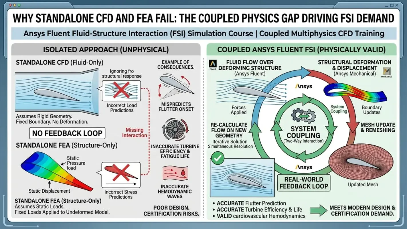
This limitation carries serious consequences. An aeroelastic analysis treating a wing as rigid will mispredict flutter onset. A hydropower turbine simulation ignoring blade deformation will produce inaccurate efficiency and fatigue life data. A cardiovascular FSI model applying static pressure cannot capture hemodynamic wave propagation. Industry demand for engineers capable of executing two-way FSI simulations using Ansys System Coupling has grown sharply — because the consequences of single-physics approximation are no longer acceptable in modern design and certification workflows.
Technical Core Competencies & Coupled Solver Mastery in Ansys FSI Simulation
Technical Simulation Skills:
Configuring one-way FSI data transfer from Ansys Fluent to Ansys Mechanical
Setting up and managing two-way FSI using Ansys System Coupling
Implementing intrinsic FSI with the embedded Structure model within Fluent
Modeling linear elasticity and nonlinear large-deformation structural behavior
Performing stress, strain, and displacement analysis under coupled fluid loading
Interpreting transient FSI results including deformation history and pressure evolution
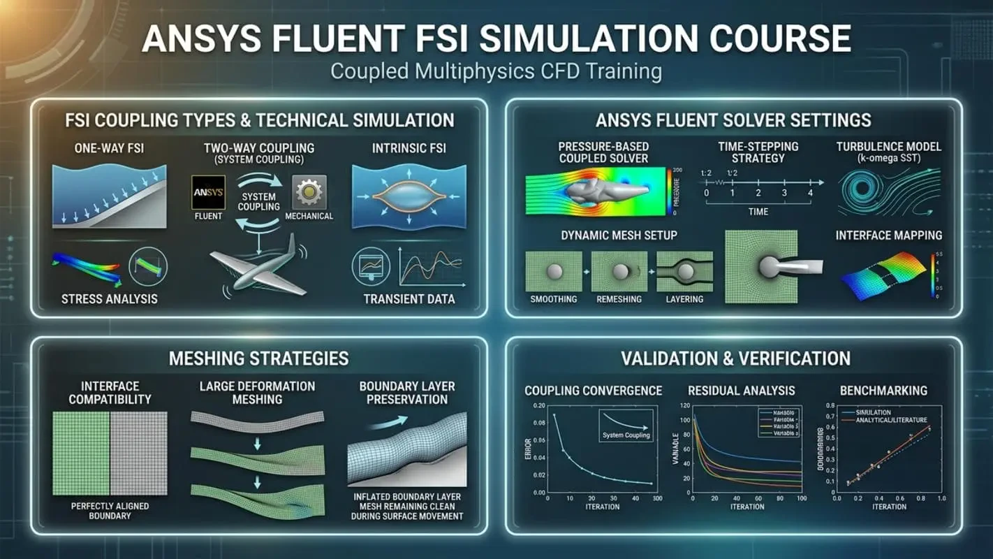
Ansys Fluent Solver Settings:
Pressure-based coupled solver configuration for incompressible FSI flows
Transient time-stepping strategy for coupled simulation stability
Dynamic mesh setup — smoothing, remeshing, and layering methods
Turbulence model selection (e.g., k-omega SST for wall-bounded and separated flows)
Boundary condition mapping at the fluid-solid interface
Meshing Strategies:
Interface mesh compatibility between Fluent and Mechanical domains
Mesh morphing and remeshing for large structural deformations
Boundary layer mesh preservation during dynamic deformation cycles
Validation & Verification Skills:
Coupling convergence monitoring within System Coupling iterations
Residual analysis across both fluid and structural solvers
Benchmarking FSI results against analytical solutions and published literature
Comprehensive FSI Simulation Projects & Engineering Milestones
FSI Physics Foundations: Governing Equations and Coupling Methodology
Before configuring any coupled solver, engineers must internalize the governing equations of fluid-structure interaction. This milestone covers the Navier-Stokes equations for the fluid domain and elastodynamic equations for structural stress and deformation, unified through the Arbitrary Lagrangian-Eulerian (ALE) framework that allows the fluid mesh to deform with structural boundary motion. The distinction between weak coupling (sequential data transfer) and strong coupling (iterative within-step convergence) is established with quantitative accuracy criteria — giving engineers the decision framework for selecting the correct coupling methodology for any given problem.
Ansys System Coupling Workflow: Two-Way FSI Data Transfer and Transient Solver Configuration
This milestone targets the most industrially relevant FSI architecture: the Ansys System Coupling framework connecting Ansys Fluent and Ansys Mechanical. Learners configure participant solvers, establish data transfer connections for surface pressure, total force, and nodal displacement, and set coupling time step controls. The engineering challenge is ensuring interface data transfer is spatially accurate across non-conformal meshes and temporally stable through sub-iteration convergence. This workflow directly mirrors the methodology used in aerospace structural certification, offshore riser analysis, and industrial heat exchanger design.
Intrinsic FSI Using the Ansys Fluent Structure Model
Not every coupled fluid-solid problem requires full System Coupling overhead. This milestone introduces intrinsic FSI — where structural calculations are performed within Ansys Fluent using the embedded Structure model, eliminating the need for a separate Mechanical instance. Learners configure material properties, structural boundary conditions, and coupling parameters entirely within Fluent. The project investigates linear elastic membrane and shell-type structures under fluid pressure loading, and develops the engineering judgment to distinguish when intrinsic FSI is physically adequate versus when full two-way System Coupling is required.
Fish Cage Hydrodynamic FSI: Offshore Marine Engineering Simulation
This project simulates a flexible fish cage structure subjected to ocean current hydrodynamic loading — a canonical problem in offshore engineering and aquaculture structural design. Learners apply two-way FSI to resolve the mutual interaction between oscillating fluid forces and the large nonlinear deformation of cage netting and mooring systems. The k-omega SST turbulence model captures complex separated flow around the flexible structure. Engineering outputs include structural displacement fields, maximum stress locations, and deformation-induced drag coefficient changes — critical parameters for offshore structural integrity assessment.
Airfoil Aeroelastic Analysis: Coupled Aerodynamic Load Transfer and Wing Deformation
Aeroelasticity is one of the defining challenges of aerospace engineering. This milestone executes a complete aeroelastic FSI simulation of a flexible airfoil under transient aerodynamic loading using Ansys System Coupling. Aerodynamic pressure and shear from Fluent transfer to the structural solver, where wing deformation is computed and fed back to update the fluid domain via dynamic mesh morphing. Learners analyze bending and torsional deformation, investigate how structural flexibility alters lift coefficient and pressure distribution, and identify conditions approaching aeroelastic flutter — directly applicable to aircraft design and UAV structural certification.
Water Turbine FSI Analysis: One-Way and Two-Way Coupling for Hydropower Systems
This dual-methodology project applies both one-way FSI and two-way FSI to a water turbine blade, enabling direct comparison of accuracy versus computational cost. In the one-way FSI phase, steady-state pressure from Fluent transfers to Mechanical to evaluate blade stress and deflection under nominal conditions. In the two-way FSI phase, full transient coupling captures how blade deformation modifies the local flow field, altering torque output and introducing dynamic stress cycles relevant to fatigue life prediction. This project is directly applicable to hydropower, tidal energy, and run-of-river turbine design.
Biomedical FSI Simulation: Pulsatile Blood Flow and Cardiovascular Vessel Wall Interaction
This project models pulsatile blood flow through a compliant cardiovascular vessel — a benchmark in computational hemodynamics and vascular biomechanics. Blood is configured as a non-Newtonian fluid, the vessel wall as a linear or hyperelastic structural material, and two-way FSI coupling captures the dynamic interaction between flow-induced pressure waves and vessel wall deformation. Engineering outputs include wall shear stress (WSS) distributions, radial displacement waveforms, and pressure pulse propagation velocities — clinically relevant parameters for medical device development and patient-specific surgical planning.
Professional FSI Engineering Workflow: Pre-Processing to Post-Processing
Workflow Stage | Tool / Environment | Key Technical Tasks |
|---|---|---|
Geometry & Pre-Processing | Ansys SpaceClaim / DesignModeler | Fluid domain extraction, structural body definition, interface surface identification, named selection assignment |
Meshing Strategy | Ansys Meshing | Boundary layer inflation, interface mesh compatibility, dynamic mesh zone definition, mesh quality verification |
FSI Coupling Setup | Ansys System Coupling / Workbench | Participant solver registration, data transfer variable mapping, coupling time step and iteration control |
CFD Solver Configuration | Ansys Fluent | Pressure-based coupled solver, transient formulation, k-omega SST turbulence model, dynamic mesh activation |
Structural Solver Configuration | Ansys Mechanical | Material property assignment (linear/nonlinear elasticity), structural boundary conditions, large deformation setting |
Post-Processing & Validation | Ansys CFD-Post / Mechanical Results | Deformation animation, stress and strain contour extraction, pressure-displacement correlation plots, convergence review |
Real-World Industrial Applications & Career Impact of FSI Simulation Expertise
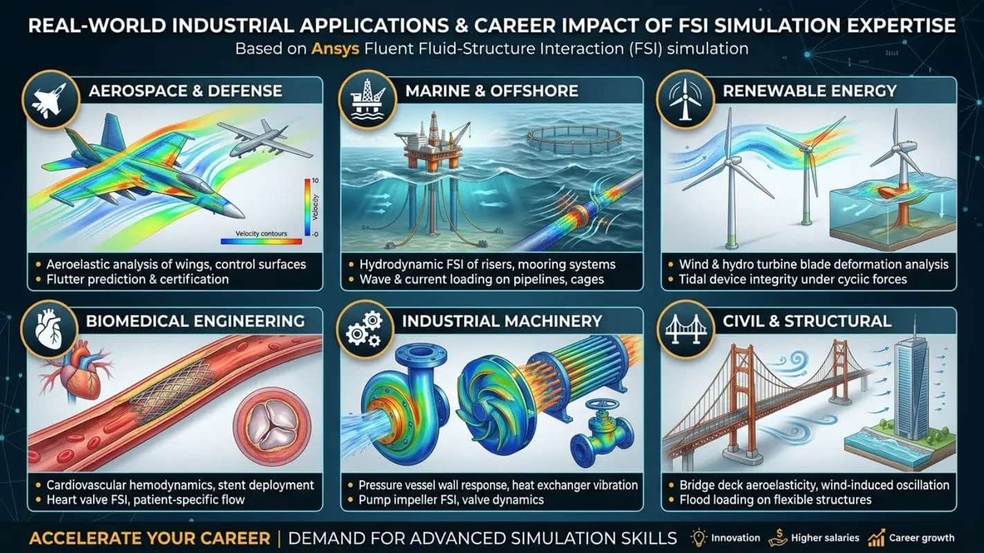
Aerospace & Defense: Aeroelastic analysis of aircraft wings, control surfaces, and UAV structures; flutter prediction and structural certification under aerodynamic loading
Marine & Offshore Engineering: Hydrodynamic FSI of offshore risers, mooring systems, flexible fish cages, and subsea pipelines under wave and current loading
Renewable Energy: Wind and hydropower turbine blade deformation analysis, tidal energy device structural integrity under cyclic hydrodynamic forces
Biomedical Engineering: Cardiovascular hemodynamics, stent deployment simulation, heart valve FSI, and patient-specific vascular flow analysis
Industrial Machinery: Pressure vessel wall response, heat exchanger tube vibration, pump impeller FSI, and valve dynamics under high-velocity flow
Civil & Structural Engineering: Bridge deck aeroelasticity, wind-induced oscillation of tall structures, and flood-induced loading on flexible barriers
Target Audience: Who Should Enroll in This Ansys FSI CFD Training
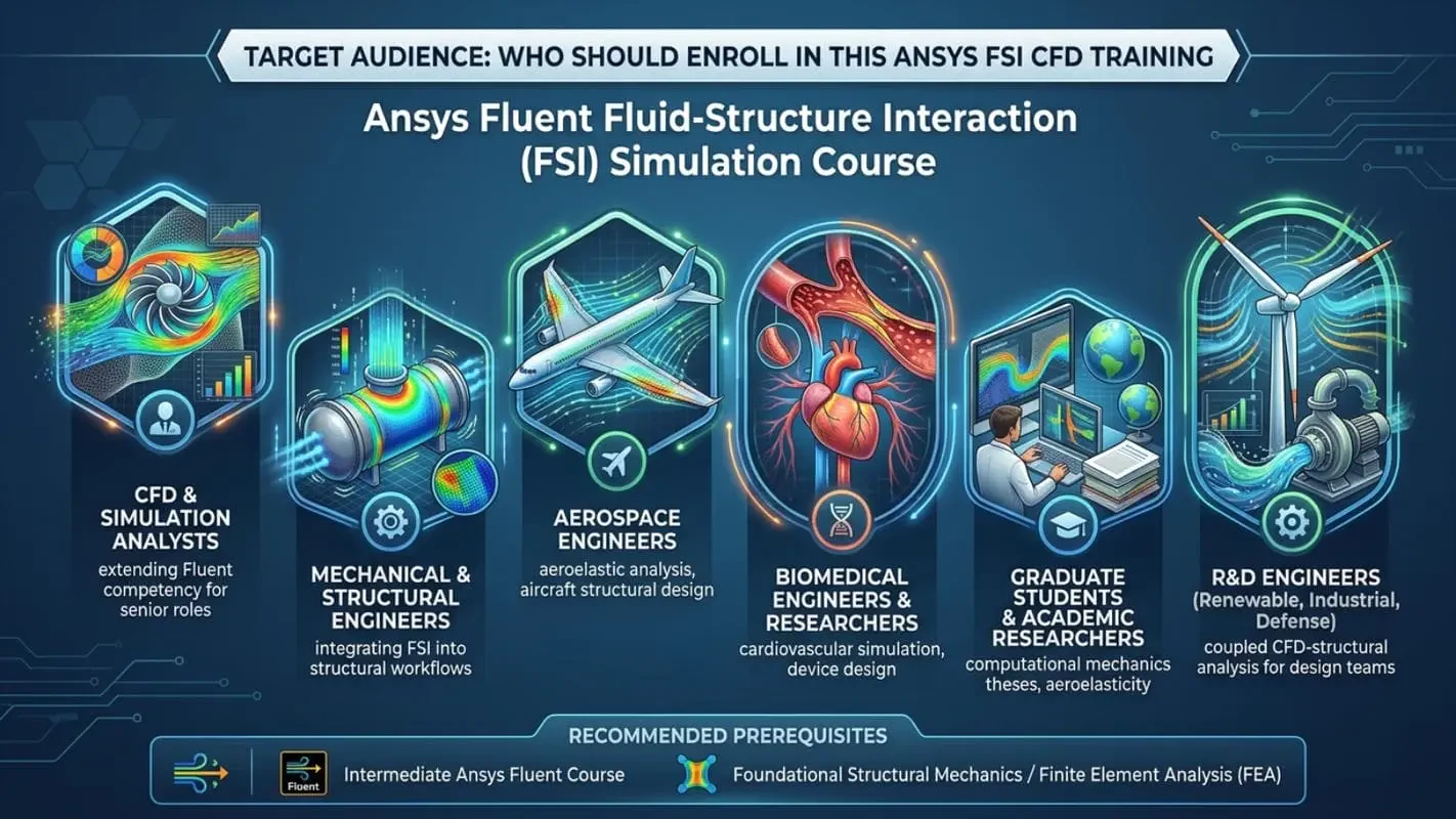
CFD Engineers & Simulation Analysts extending Ansys Fluent competency into coupled multiphysics domains and targeting senior simulation roles
Mechanical & Structural Engineers working with fluid-loaded systems who need to integrate FSI methodology into structural integrity workflows
Aerospace Engineers involved in aeroelastic analysis, aircraft structural design, or UAV development requiring validated Ansys FSI capability
Biomedical Engineers & Researchers working on cardiovascular simulation, medical device design, or patient-specific hemodynamic modeling
Graduate Students & Academic Researchers pursuing theses in computational mechanics, aeroelasticity, biomechanics, or offshore engineering
R&D Engineers in renewable energy, industrial machinery, or defense delivering coupled CFD structural analysis to design teams and regulatory bodies
Recommended prerequisites include completion of the intermediate Ansys Fluent course and foundational knowledge of structural mechanics or finite element analysis.
The MR CFD Authority: Production-Grade FSI Training You Can Trust
MR CFD brings over 15 years of combined consulting and training expertise across industrial and academic CFD simulation environments. Every simulation project in this course reflects the same engineering rigor applied in active CFD consulting engagements — where coupled multiphysics FSI simulation is routinely delivered to aerospace manufacturers, energy companies, and biomedical research institutions.

All projects use production-grade mesh densities, physically validated boundary conditions, and industry-standard convergence criteria. AI-assisted technical support provides rapid, context-aware guidance on solver settings, coupling configuration, and result interpretation. For computationally intensive two-way FSI simulations, MR CFD’s ANSYS HPC Servers provide the parallel computing infrastructure to execute large-scale transient coupled simulations efficiently — eliminating the hardware barrier that limits learning in traditional academic settings. Engineers seeking applied project experience can further develop their portfolios through the CFD Internship Program.
Educational Progression & Next Steps in Your Multiphysics CFD Career

The Ansys Fluent FSI Simulation Course occupies the advanced tier of the MR CFD structured learning pathway. Engineers new to Ansys Fluent should begin with the Ansys Fluent Beginner Course, which establishes foundational solver literacy — geometry preparation, meshing, boundary condition setup, and basic post-processing. The Ansys Fluent Expert Course delivers advanced solver configuration — UDF programming, complex turbulence modeling, and multiphase flows — that complements FSI expertise for engineers targeting the highest levels of simulation capability.
Upon completing this FSI course, recommended advanced specialization tracks include:
Computational Aeroelasticity — nonlinear flutter analysis and gust response simulation
Computational Hemodynamics — patient-specific cardiovascular modeling and medical device regulatory simulation
Offshore Structural Dynamics — wave-structure interaction and fatigue life prediction under stochastic loading
Renewable Energy Multiphysics — combining FSI with thermal and electromagnetic coupling for next-generation turbine design
Enroll Now & Build Your Coupled Simulation Engineering Expertise
The ability to simulate how fluids and structures interact under real operating conditions is a foundational competency for engineers working at the frontier of aerospace, energy, biomedical, and marine design. The Ansys Fluent FSI Simulation Course from MR CFD delivers this competency through structured, project-driven training that mirrors professional engineering standards.
You will leave this course able to configure Ansys System Coupling two-way FSI workflows, execute intrinsic FSI simulations, manage dynamic mesh deformation, interpret coupled stress-deformation-flow results, and apply FSI methodology to real industrial challenges. Explore the full range of available programs at the Ansys Fluent Full Courses list hub and enroll today — position yourself at the technical vanguard of coupled multiphysics simulation engineering.
Fluid-Structure Interaction is a multiphysics simulation approach that analyzes how fluid flow and structural deformation influence one another.
One-Way FSI transfers fluid loads to the structure only, while Two-Way FSI exchanges information continuously between fluid and structural solvers.
System Coupling is a framework that enables data transfer between CFD and structural solvers during coupled analyses.
Intrinsic FSI performs fluid and structural calculations within a unified simulation environment without relying on external coupling tools.
Aerospace, marine, biomedical, renewable energy, automotive, and industrial engineering industries frequently use FSI methodologies.
Many engineering systems experience mutual interaction between fluid forces and structural response, making standalone simulations insufficient.
Yes. FSI is widely used to analyze blood vessels, heart valves, medical devices, and cardiovascular systems.
Yes. The course includes fish cages, airfoils, water turbines, blood vessels, and other real-world FSI applications.
You will learn coupled CFD-structural analysis, system coupling workflows, intrinsic FSI techniques, deformation analysis, and multiphysics engineering simulation.
Many engineers continue with advanced multiphysics topics such as aeroelasticity, hydroelasticity, nonlinear material behavior, fluid-thermal-structural coupling, and high-fidelity research-level FSI simulations.