

Agricultural & Food: Beginner CFD Training Package
Price: $29
Learn CFD in Agriculture through 10 hands-on ANSYS Fluent projects
Simulate greenhouse microclimate cfd for spraying & ventilation design
Master porous medium seed drying cfd for food processing applications
Build skills in irrigation modeling, crop spraying, and water management
Covers VOF, Eulerian multiphase, DPM, and porous media (Darcy-Forchheimer)
Designed for agritech engineers, R&D teams, and farming equipment designers
Agricultural & Food: Beginner CFD Training Package
Price: $29
Learn CFD in Agriculture through 10 hands-on ANSYS Fluent projects
Simulate greenhouse microclimate cfd for spraying & ventilation design
Master porous medium seed drying cfd for food processing applications
Build skills in irrigation modeling, crop spraying, and water management
Covers VOF, Eulerian multiphase, DPM, and porous media (Darcy-Forchheimer)
Designed for agritech engineers, R&D teams, and farming equipment designers
-
When water spills over an ogee overflow and discharges into a pond, the way it behaves depends heavily on whether the flow runs as a free surface or under pressure. Capturing that difference is essential for designing spillways and overflow structures that handle their intended flow safely. In this project, you'll use ANSYS Fluent to simulate water flowing over an ogee spillway into a pond, comparing two distinct flow regimes side by side. The model is built in two dimensions in ANSYS DesignModeler as an ogee overflow leading into a pond, and two separate cases are studied. In the first, the flow is a free surface reaching the overflow at a defined height with a flow rate of 140 kg/s; in the second, the water flows under pressure with a flow rate of 420 kg/s. The geometry is also configured in two variants — one that includes an upstream region before the overflow and one that omits it — and the inlet is split into separate water-flow and airflow sections. Meshing is carried out in ANSYS Meshing using a semi-structured grid, with roughly 20,100 elements for the free-flow case and 16,400 for the pressure-flow case. Because both cases involve a moving interface between air and water, a two-phase Volume of Fluid (VOF) model is used, with air defined as the primary phase and water as the secondary phase. From the results, you'll examine 2-D contours of pressure and velocity along with the volume-fraction field that reveals the free surface and the path of the water into the pond. You'll also obtain a plot of static pressure along the flow direction for both models, allowing a direct comparison between the free-surface and pressurized regimes. By the end of this project, you'll be able to set up a two-phase free-surface flow in ANSYS Fluent using the VOF model, configure and compare multiple flow scenarios on a single hydraulic structure, and interpret the results to understand how overflow conditions change pressure and velocity behavior.
Lesson 1 12m 23s -
Mastering Hydraulic Structure Analysis: Ogee Spillway CFD Simulation for Beginners Welcome to the “Ogee Spillway CFD Simulation” episode of our “HYDRAULIC Engineers: BEGINNER” course. This comprehensive module introduces civil engineers to the powerful world of computational fluid dynamics (CFD) applied to spillway design and analysis. Learn how to leverage ANSYS Fluent to simulate and analyze the complex flow characteristics of ogee spillways, a critical component in modern dam engineering and flood control systems. Understanding the Importance of Ogee Spillways in Hydraulic Engineering Before diving into the simulation specifics, let’s explore the fundamental concepts of ogee spillways and their significance in dam engineering. The Role of Spillways in Dam Safety and Flood Control Discover how spillways contribute to water level regulation and dam safety, and why understanding their hydraulic behavior is crucial for effective flood management. Advantages of Ogee-Shaped Spillways in Energy Dissipation Learn about the unique characteristics of ogee spillways that make them highly efficient in dissipating energy and controlling water flow in dam structures. Introduction to ANSYS Fluent for Spillway Analysis This section focuses on familiarizing beginners with the ANSYS Fluent software environment: Navigating the ANSYS Fluent Interface Gain insights into the basic layout and functionality of ANSYS Fluent, essential for efficient simulation setup and analysis of hydraulic structures. Understanding the CFD Workflow for Spillway Simulations Learn the step-by-step process of setting up, running, and analyzing an ogee spillway CFD simulation in ANSYS Fluent. Setting Up a Basic Ogee Spillway Model Master the art of creating a simple simulation environment for spillway hydraulics: Defining Geometry and Mesh for Ogee Spillway Simulations Learn techniques for creating a basic geometry representing an ogee spillway, along with appropriate meshing strategies for accurate flow analysis. Configuring Water Properties in ANSYS Fluent Explore methods for defining and implementing the properties of water in your spillway flow simulation. Boundary Conditions for Spillway Flow Scenarios Dive into the critical settings that ensure realistic representation of water flow over ogee spillways: Specifying Inlet and Outlet Conditions Understand how to set up appropriate inlet flow rates and outlet pressure conditions that accurately represent spillway operation scenarios. Implementing Wall and Free Surface Boundary Conditions Learn to define proper boundary conditions for the spillway surface and water-air interface to capture realistic flow behavior. Running Simple Simulations of Water Flow Over an Ogee Spillway Develop skills to execute and monitor your first ogee spillway CFD simulations: Setting Up Solver Parameters for Hydraulic Simulations Master the basics of configuring solver settings, including time-stepping and convergence criteria, suitable for spillway flow simulations. Monitoring Simulation Progress and Ensuring Stability Learn techniques for tracking simulation progress and identifying potential issues during the solving process. Analyzing Basic Velocity Distributions and Pressure Profiles Develop expertise in extracting meaningful insights from your spillway simulations: Visualizing Water Flow Patterns Over the Spillway Master techniques for creating insightful visualizations of velocity fields and streamlines to understand flow behavior along the ogee profile. Interpreting Pressure Distributions on Spillway Surfaces Learn to analyze pressure profiles along the spillway surface, crucial for assessing hydraulic loads and potential cavitation risks. Understanding Energy Dissipation in Ogee Spillways Explore the fundamentals of energy dissipation, a key function of ogee spillways: Principles of Energy Dissipation in Hydraulic Structures Gain insights into how ogee spillways effectively dissipate energy from high-velocity flows, protecting downstream structures. Analyzing Energy Dissipation Patterns in CFD Results Learn introductory methods for identifying and interpreting energy dissipation characteristics in your simulation results. Practical Applications and Civil Engineering Relevance Connect simulation insights to real-world spillway design challenges: Applying CFD Insights to Spillway Design and Analysis Explore how the flow patterns and pressure distributions observed in CFD simulations can inform spillway design decisions and performance assessments. Understanding the Limitations of Beginner-Level Simulations Gain awareness of the simplifications in this introductory course and the potential for more advanced analyses in future studies. Why This Module is Essential for Beginner Hydraulic Engineers This beginner-level module offers an introduction to the powerful world of CFD in hydraulic structure analysis. By completing this simulation, you’ll gain valuable insights into: Basic application of ANSYS Fluent for simulating water flow over ogee spillways Essential CFD techniques for capturing flow patterns and pressure distributions in spillway structures Practical applications of CFD analysis in spillway design and performance evaluation By the end of this episode, you’ll have developed foundational skills in: Setting up and running basic spillway flow simulations using ANSYS Fluent Interpreting simulation results to assess hydraulic characteristics of ogee spillways Applying CFD insights to enhance understanding of spillway performance and inform design decisions This knowledge forms a solid foundation for civil engineers looking to integrate advanced computational methods into their hydraulic structure design and analysis toolkit, providing a springboard for more advanced studies in dam engineering and flood control systems. Join us on this exciting journey into the world of ogee spillway CFD simulation, and take your first steps towards becoming a proficient hydraulic engineer equipped with cutting-edge computational tools for spillway analysis and design!
Lesson 2 12m 40s -
This project simulates the two-phase flow of water and air over an ogee spillway — the curved overflow structure used in dams to pass excess water safely downstream. When flow meets an obstruction, the water level rises behind it and accelerates over the crest; an ogee profile is shaped specifically to match the natural nappe of falling water, minimizing pressure problems and maximizing discharge efficiency. Capturing the free water surface as it spills over the crest is the core of the problem and a classic application of free-surface CFD in civil and hydraulic engineering. The physics is handled with the Volume of Fluid (VOF) multiphase model, which tracks the sharp air–water interface as it deforms over the spillway, with standard k-ε closing the turbulence. Because the whole point is to watch the water move, accelerate, and form its surface profile over the crest, the case is solved transient. Setup: water enters the computational domain at a mass flow rate of 0.05 kg/s and flows over the spillway against the air phase. Geometry is built in ANSYS Design Modeler and meshed in ANSYS Meshing with a structured mesh (12,846 elements) — structured here because the spillway's smooth, well-defined geometry suits a clean, aligned grid along the flow path. What the results show: contours of pressure, velocity, and phase volume fraction extracted across the domain, revealing the water surface profile over the crest, the acceleration of the flow down the spillway face, and the pressure distribution along the structure — exactly the quantities a hydraulic engineer uses to assess discharge capacity and surface pressures. Included: Geometry & Mesh file, plus a comprehensive training movie walking through the full setup, solution, and extraction of all results. You'll learn to: set up a transient VOF air–water free-surface case, define mass-flow inflow over a curved spillway, apply standard k-ε turbulence, and read the free-surface profile and pressure field from volume-fraction and pressure contours.
Lesson 3 19m 39s -
Spillway CFD Simulation Description In this project, a three-dimensional spillway is simulated using ANSYS Fluent to study how excess water is managed and released from a dam structure. Spillways serve as the outlet mechanism for a dam, designed to safely carry surplus water and floodwater from the reservoir side down to the downstream side once the water level rises past a defined threshold. Because agricultural water management relies heavily on dams and reservoirs for irrigation supply, understanding spillway hydraulics is directly relevant to agricultural and food engineering applications, where controlled water release protects both the structure and the farmland downstream. Several spillway designs exist, including ogee-shaped, stepped, side-channel, lotus, tunnel, and siphon spillways. This project focuses on simulating the flow behavior over one such spillway geometry using a multiphase approach, treating air as the primary phase and water as the secondary phase. In the model setup, the water column at the inlet reaches a height of 0.155 m, while the full model height is 0.306 m, and the dam structure itself has a height of 0.156 m. The three-dimensional geometry was built in Design Modeler, and the mesh was generated in ANSYS Meshing using an unstructured mesh strategy, resulting in a total of 698,691 elements. Methodology The two-phase air-water interaction is captured using the Volume of Fluid (VOF) multiphase model. Gravity is applied along the y-axis at a magnitude of -9.81 m/s² to correctly represent the driving force behind the water's downward flow over the spillway. Conclusion The resulting flow contours confirm that the spillway performs as intended, allowing the water to pass over the structure smoothly. The highest flow velocities appear where the flow cross-section narrows, since the water accelerates as it's forced through the tighter geometry — a behavior consistent with what's expected in real spillway operation and useful for engineers designing water release systems for agricultural reservoirs.
Lesson 4 21m 19s -
Stepped Spillway CFD Simulation — Attain Elite Mastery in ANSYS Fluent Description Agricultural & Food Engineering: energy dissipation and aeration in irrigation and farm water-delivery infrastructure. This module covers CFD simulation of stepped (stair) spillways used in farm reservoirs, irrigation-scheme headworks, and aquaculture pond overflow structures. Stepped spillways dissipate flow energy in stages as water descends, reducing erosion risk in earthen irrigation channels and downstream fields, while promoting air entrainment that raises dissolved-oxygen levels for aquaculture systems fed by the discharge. Part of Course 9, "Attain Elite Mastery in ANSYS Fluent" — an advanced-level treatment for engineers ready to move past basic setup into rigorous multiphase and turbulence analysis. Simulation Methodology The stepped-spillway profile is modeled with a refined near-wall mesh to resolve recirculation within each step cavity, representing a farm reservoir or irrigation-scheme drop structure. A VOF (Volume of Fluid) formulation captures the water-air free surface, including entrained air pockets forming within the cavities, while RNG k-ε and SST k-ω turbulence models are compared for accuracy in the skimming-flow regime typical of these structures. Sediment-laden agricultural runoff is coupled in via a discrete-phase or mixture-model treatment, relevant to canal and reservoir sediment management. Inlet flow rates and outlet pressure are set to represent peak irrigation-season release and seasonal flood scenarios, with wall and free-surface boundary conditions defined for the water-air interface. The solver runs transient time-stepping with tight convergence criteria to keep the free-surface and air-entrainment tracking stable. Results & Conclusion Velocity fields and streamlines along the stepped profile show progressive energy dissipation across the skimming-flow regime, with air entrainment and aeration efficiency quantified per step — directly informing downstream aquaculture dissolved-oxygen outcomes. Energy dissipation and residual downstream energy are calculated to size scour protection for canal linings and downstream fields, and sediment transport behavior along the steps is analyzed to support reservoir sediment-management planning. At this advanced level, the results support production-grade design of irrigation and farm reservoir spillway structures, going beyond qualitative flow visualization into quantitative design guidance.
Lesson 5 20m 58s -
Hydraulic Jump of Water in a Rectangular Channel — ANSYS Fluent CFD Simulation A hydraulic jump is what happens when fast, shallow water abruptly slows down: the flow height rises sharply, velocity drops, and energy is dissipated in a turbulent transition. It's a key phenomenon in open-channel and agricultural water systems — spillways, irrigation canals, and energy-dissipation structures all rely on understanding where and how strongly a jump forms. This project uses ANSYS Fluent to capture that transition and locate exactly where the jump occurs for two different inlet flow rates. The water–air system is modeled with the VOF (Volume of Fluid) multiphase approach, which tracks the free surface between the flowing water and the surrounding ambient air. The fluid domain is built in Design Modeler, and a structured mesh of 231,646 elements is generated in ANSYS Meshing. The case is solved as a steady, pressure-based simulation with gravity included (−9.81 m/s² in the Y-direction). Turbulence is modeled with the standard k-ε model using standard wall treatment, and the VOF model runs with implicit volume-fraction formulation and implicit body forces over two Eulerian phases (air and water). Air enters through a pressure inlet at zero gauge pressure, while water enters through a mass flow inlet. The simulation is run for two inlet water flow rates to compare their effect on the jump. Pressure–velocity coupling uses the SIMPLE scheme, with PRESTO! for pressure, second-order upwind for momentum, and Modified HRIC for the volume fraction. The results show the hydraulic jump forming at different downstream locations depending on flow rate: the jump occurs about 0.9 m downstream for the lower flow rate and about 2.8 m downstream for the higher one — the stronger flow carries its momentum farther before transitioning. By the end of this project, you'll be able to set up a free-surface VOF simulation, configure the appropriate solver and discretization schemes for two-phase open-channel flow, and predict where a hydraulic jump forms as a function of inlet conditions.
Lesson 6 26m 45s -
Description This project simulates the three-phase flow of water, air, and sand over a circular weir using ANSYS Fluent, investigated through CFD analysis. When an obstacle is placed in the path of a flow, it causes the fluid level to rise behind it and the velocity to increase, eventually leading the fluid to spill over the obstacle; structures of this kind are known as weirs. Weirs take various forms depending on their intended use and are widely employed in civil and agricultural water management — for controlling and measuring flow in irrigation channels, canals, and other water-conveyance systems central to agriculture. The model was built in 2D using SpaceClaim. Meshing was performed in ANSYS Meshing, producing 4,770 elements. Methodology In this simulation, water enters the computational domain at a velocity of 1 m/s and flows over a sand bed situated behind the weir. As it passes over the weir, the flow lifts some of the sand and carries it downstream. The standard k-epsilon model is used to solve the turbulent flow equations, while the Eulerian multiphase model is employed to capture the motion of and interaction between the three phases — water, air, and sand. Conclusion On completion of the solution, two-dimensional contours of the volume fraction of the air, water, and sand phases, along with pressure, streamlines, and velocity vectors, were obtained. As the sand volume fraction contour shows, the water flow lifts a portion of the sand from the bed and transports it as it spills over the weir. Over the long term, the sand bed behind the weir is washed away entirely, and the emptied region behind the circular obstacle becomes a tangential path for the water — illustrating the sediment-transport and scouring behavior that is important when designing weirs for irrigation and agricultural water systems.
Lesson 7 13m 37s -
Description This project simulates the operation of a lawn sprinkler using ANSYS Fluent, investigated through CFD analysis. Efficient irrigation is a central concern of agricultural engineering, and understanding how water is thrown from a sprinkler and distributed over the ground surface is key to designing systems that water lawns and crops evenly. The system involves two fluids: air as the primary phase and water as the secondary phase, modeled with the Eulerian multiphase approach. The water jet enters the domain at a velocity of 0.5 m/s, with gravity included at −9.81 m/s² along the y-axis. Geometry & Mesh The 2D geometry was created in Design Modeler. Meshing was performed in ANSYS Meshing using an unstructured grid with no element quality below 0.54, giving a total cell count of 19,203,911. Methodology Several assumptions underpin the simulation: the solver is pressure-based and transient; only the fluid behavior is examined, so heat transfer is not modeled; and gravity acts at 9.81 m/s² along the y-axis. Viscous model — k-omega SST with the shear-flow correction option Multiphase model — Eulerian, with air as the primary phase and water as the secondary phase, using the explicit formulation Boundary conditions — Inlet: velocity inlet with an initial mixture gauge pressure of 0, a water velocity magnitude of 0.5 m/s, and a water volume fraction of 1; Outlet: pressure outlet with backflow volume fractions of 1 for air and 0 for water; Walls: stationary Methods — phase-coupled pressure-velocity coupling; PRESTO! for pressure; first-order upwind for momentum, specific dissipation rate, and volume fraction Initialization — standard method, with a water velocity of 0.5 m/s in the y-direction, zero air velocity, and a secondary-phase (water) volume fraction of 1 Conclusion On completion of the solution, two- and three-dimensional results for velocity and for the air and water volume fractions were obtained, along with an animation of the process. The simulation shows the water leaving the sprinkler nozzle, reaching the spreader fin, and — as time progresses — falling to the ground and spreading across the surface. This captures how the sprinkler distributes water over the lawn, providing insight useful for designing and optimizing irrigation systems in agricultural applications.
Lesson 8 11m 13s -
This project simulates a greenhouse roof watering system — water sprayed from roof-mounted nozzles falling through air and accumulating on the surface below. It's a clean introduction to two-phase flow under gravity, where the goal is to track where the water goes and how it distributes once it leaves the nozzle. The case is built as a 2-D transient model in Design Modeler, with the domain split into two sections: a resident pool of water at the bottom and an upper region carrying a velocity inlet and an outlet. The tank sides are treated as walls. Meshing is done in ANSYS Meshing (~208,921 elements). Physics is handled with the Eulerian multiphase model, using air as the primary phase and water as the secondary phase. Water enters at 0.3 m/s with gravity acting at −9.81 m/s² on the y-axis, and turbulence is closed with the SST k-ω model. Because the spray develops over time — water pumping out, falling, and pooling — the solver is run transient. What the results show: velocity fields and air/water volume-fraction contours capture the full sequence — water pumping through the roof nozzles, dropping under gravity, and spreading across the bottom surface. The volume-fraction field is the key output: it shows coverage and where water collects, which is exactly what you'd tune in a real irrigation layout. You'll learn to: set up a 2-D transient Eulerian two-phase case, define primary/secondary phases, apply gravity correctly, and read phase distribution from volume-fraction contours.
Lesson 9 10m 56s -
Drying Seed Behavior in a Porous Medium — ANSYS Fluent CFD Simulation This project investigates the drying process of seeds within a semi-cylindrical domain packed with seed particles, using ANSYS Fluent to capture the coupled heat and mass transfer occurring as hot air flows through the seed bed. The simulation tracks temperature, moisture distribution, and velocity fields within the porous seed zone to evaluate how the drying process evolves over time under given thermal and flow conditions, offering insight into drying efficiency, local heat transfer, and vapor concentration patterns. Geometry and Mesh The geometry was built using ANSYS SpaceClaim and DesignModeler. Taking advantage of symmetry, only half of the physical domain was modeled, with the bottom surface defined as a symmetry boundary to reduce computational cost. Two zones were defined: a fluid zone representing the drying air, and a seed zone treated as a porous medium with a porosity of 0.418, reflecting the physical packing of the seeds. The domain was discretized in ANSYS Meshing using a tetrahedral mesh of approximately 4.5 million cells, providing sufficient resolution to resolve the temperature and velocity gradients around the seed particles. Model and Solver Settings A pressure-based transient solver was used to capture the time-dependent heat and mass transfer behavior, with gravity set to -9.81 m/s² in the Y-direction to correctly account for buoyancy. The energy equation was activated to model heat exchange between the hot air and the seed surfaces, and the RNG k-ε turbulence model was selected for its accuracy in capturing recirculating and swirling flows within porous media. The species transport model was enabled to track water vapor (H₂O) concentration, with air, H₂O, and wheat defined as the working materials. Pressure-velocity coupling was handled using the SIMPLEC algorithm, with a velocity inlet for the incoming hot air and a pressure outlet for the exiting flow. The transient formulation allowed the temperature and moisture fields within the seed zone to be monitored over time. Results The temperature contours show a gradual rise across the seed bed, with values ranging from approximately 302.6 K to 303.1 K, indicating a gentle but effective drying process. The H₂O mass fraction contours show a progressive decrease in vapor concentration along the airflow path, confirming that moisture is being removed from the seed surfaces. Velocity streamlines show the air accelerating as it passes through the porous region, enhancing convective heat and mass transfer. Together, the flow, temperature, and species fields indicate that the airflow is well distributed through the porous bed, promoting uniform drying conditions throughout the domain. These results can help guide the optimization of airflow velocity, porosity, and inlet temperature for improved drying performance in industrial applications.
Lesson 10 20m 5s
CFD in Agriculture Course: Beginner Training Course for Applied Agritech Engineers
Most search results for CFD in Agriculture point toward academic papers and university lecture notes. This course from MR CFD (Part of CFD Online training courses) is built for the opposite audience — agritech engineers, R&D teams, and farming equipment designers who need to simulate real systems inside ANSYS Fluent (Start Learning Ansys fluent from beginner) and walk away with a working model, not a literature review. Across 10 structured projects, you’ll move from basic free-surface water flow into multiphase spray modeling and porous-media drying, the exact physics that show up when you’re trying to design better irrigation layouts or improve crop drying yields.

Every project in this package is built inside ANSYS Fluent Software, using the same interface and workflow you’d use on a commercial engineering project. The goal isn’t to explain fluid dynamics theory in the abstract — it’s to get you comfortable setting up boundary conditions, choosing the right multiphase model, and reading results in a way that’s directly transferable to farm-scale and food-processing design work.
Why This Course Bridges Theory and Applied Engineering
The phrase “CFD in agriculture” is often used in a research context, but the actual demand in the field comes from people solving concrete problems: how to keep greenhouse humidity consistent, how to model porous seed beds without a physics PhD, or how to justify a spray nozzle redesign to a client. This package treats those as engineering problems from the first module, not academic case studies.
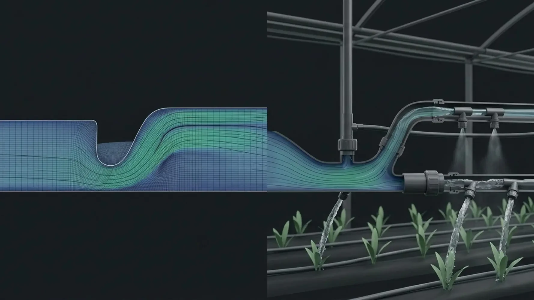
You’ll notice this in how projects are structured — each one ends with a practical takeaway (spray coverage pattern, drying rate curve, water distribution profile) rather than a purely theoretical result. If you’re coming from a background in agricultural machinery, food processing, or farm systems design, this is meant to feel like a tool-based training package, not a semester of coursework.
Course Overview & Learning Path

The 10 projects are sequenced so that each one builds on a skill introduced earlier — starting with simple free-surface flow, moving into multiphase and spray physics, and ending with porous-medium modeling.
# | Project | Core Physics Introduced | Practical Relevance |
1 | Pond Overflow | Gravity-driven free-surface flow | Foundation for water-management and drainage design |
2 | Ogee Spillway | Free-surface flow over curved geometry | Structured flow-control fundamentals |
3 | Spillway (2-D, Transient) | Transient free-surface solving | Time-dependent flow behavior |
4 | Spillway (3-D, Transient) | 3D transient free-surface flow | Full-geometry flow-control modeling |
5 | Stepped Spillway | Flow over stepped terrain | Energy dissipation in structured channels |
6 | Hydraulic Jump | Rapid open-channel flow transition | Classic free-surface phenomenon, useful reference case |
7 | Circular Weir | Eulerian 3-phase flow (air, water, sand) | Advanced multiphase water-management modeling |
8 | Watering Lawns | Spray and free-surface interaction | Irrigation system spray-coverage modeling |
9 | Water Spraying from Greenhouse Roof | Droplet trajectory, evaporation | Greenhouse microclimate and humidity control |
10 | Drying Seed Process | Porous medium, moisture diffusion | Food processing and post-harvest drying design |
Deep Dive on Agriculture CFD Course
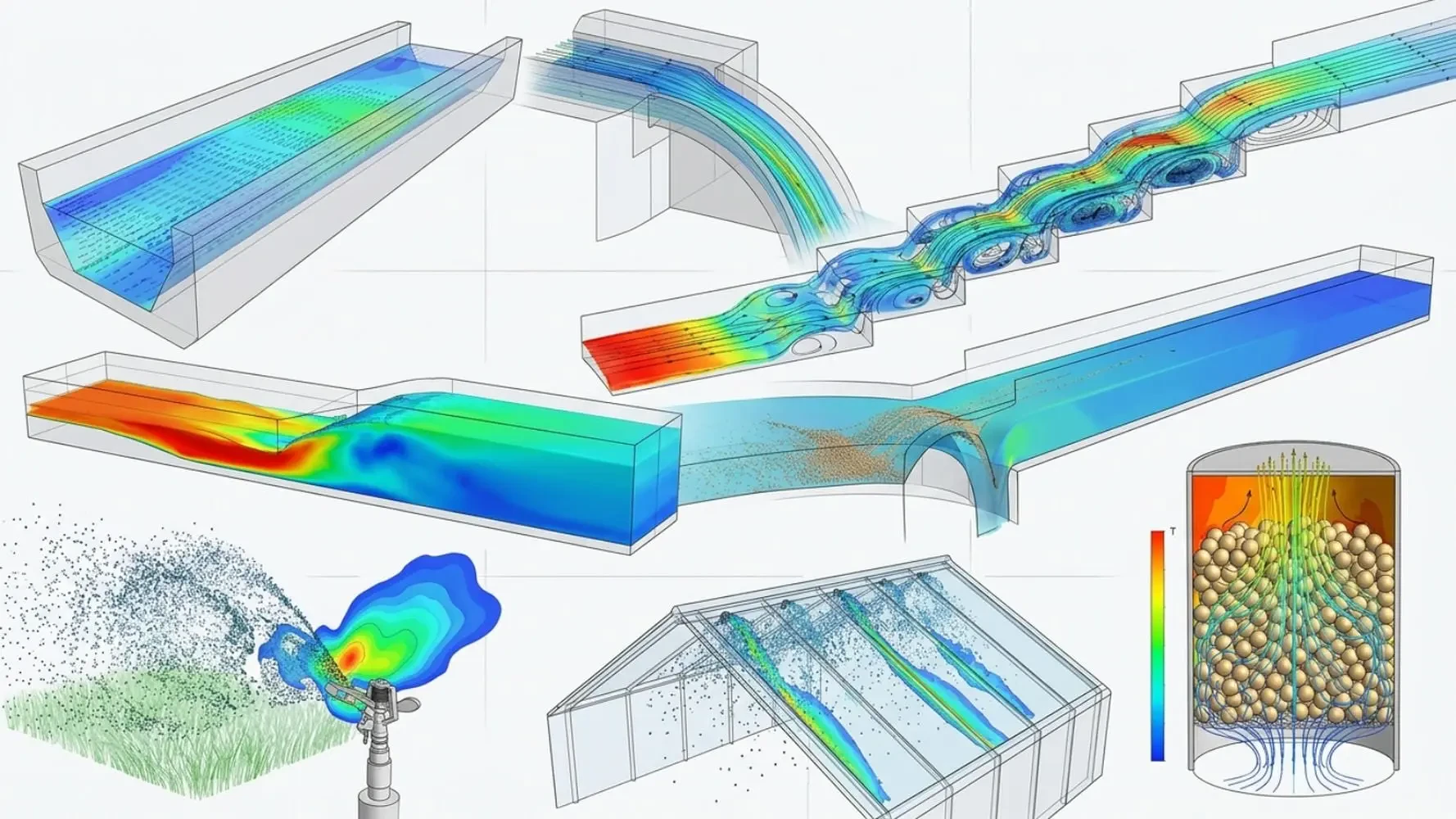
Greenhouse Microclimate & Spraying Simulation
The Water Spraying from the Roof of a Greenhouse project is where greenhouse microclimate cfd work becomes concrete. You’ll set up droplet injection from the roof, track how those droplets interact with internal air currents, and observe how spray timing affects humidity distribution across the growing space.
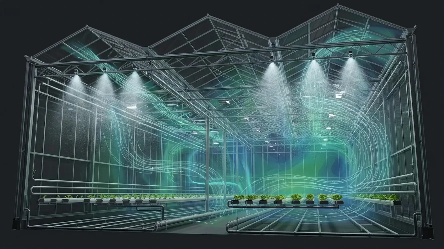
This module covers cfd simulation of greenhouse microclimate and spraying and greenhouse ventilation and spraying cfd simulation, both common problems for anyone designing climate-controlled growing environments.
Porous Medium Seed Drying
The final project, Drying Seed Process by Porous Medium, is the course’s dedicated porous medium seed drying cfd case. You’ll apply a Darcy-Forchheimer resistance formulation to represent the seed bed, then couple it with moisture diffusion and convective heat transfer to simulate a realistic drying process. This is directly applicable to cfd analysis of food dehydration and drying, and it’s structured as a self-contained module — you don’t need advanced porous-flow background going in, since the setup is built step by step from the boundary conditions up.
Irrigation and Water Management Projects
Pond Overflow and Watering Lawns together form the irrigation-focused backbone of this package, covering computational fluid dynamics for irrigation systems and giving you a working example of how to simulate watering lawns using cfd.
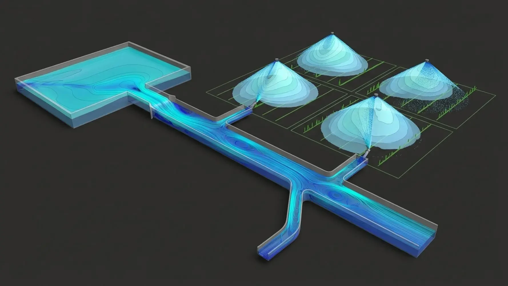
These projects also lay the groundwork for agricultural water management cfd modeling, since the free-surface and spray techniques used here scale up to farm-level irrigation design problems.
Multiphase Flow Fundamentals from the Spillway Sequence
The spillway, hydraulic jump, and circular weir projects remain in this syllabus because they build multiphase and free-surface skills that transfer directly to farm water-management design — even though this page doesn’t specifically target spillway or weir search terms (that content lives in our dedicated hydraulic structures course). The Circular Weir project specifically introduces multiphase flow air water sand agricultural applications, using a three-phase Eulerian model that’s the most demanding setup in the entire package.
Software, Solvers, and Numerical Methods in Agriculture CFD Course
All 10 projects are built in ANSYS Fluent, and across the sequence you’ll work with the following solver techniques and physics models:

Volume of Fluid (VOF) — for free-surface tracking in spillway, pond, and lawn-watering cases
Eulerian multiphase model — for the three-phase Circular Weir simulation
Discrete Phase Model (DPM) — for droplet trajectory in the greenhouse spraying project
Porous media formulation (Darcy-Forchheimer) — for the seed drying case
Turbulence modeling (k-epsilon, k-omega SST) — applied across the free-surface and channel-flow projects
Convective heat transfer and moisture diffusion — core to the drying simulation
Boundary condition setup (velocity inlet, pressure outlet) — practiced repeatedly across all 10 projects
Transient flow analysis — required for the 2D and 3D spillway modules
Drag coefficient and phase interaction settings — used in both the DPM and Eulerian cases
Sub-relaxation factor tuning — introduced as convergence issues appear in the more complex multiphase projects
Who This Course Is For
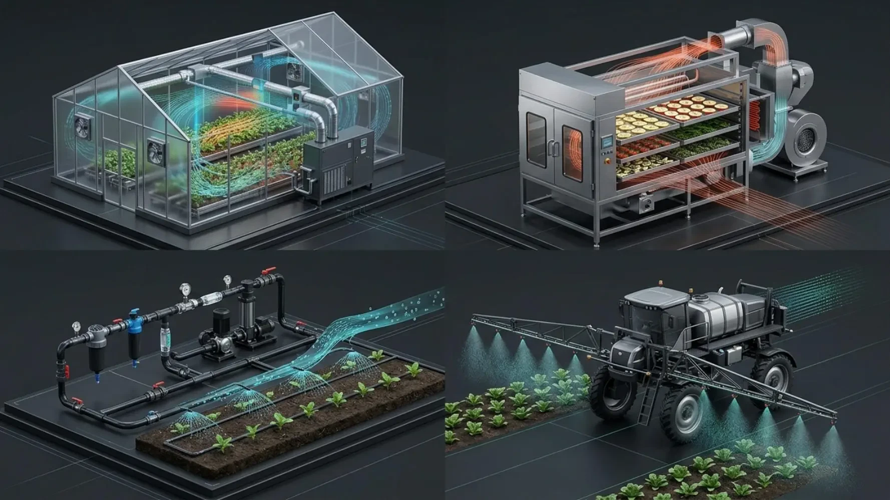
Agricultural engineers who need practical simulation skills, not theoretical background
Food processing engineers evaluating drying or dehydration equipment
R&D professionals designing irrigation, spraying, or greenhouse ventilation systems
Farming equipment designers who want to prototype spray nozzle or watering system behavior before building
CFD beginners with no prior ANSYS Fluent experience — each project is built from the interface up
No prior CFD experience is assumed. Basic familiarity with fluid mechanics terminology (flow rate, pressure, velocity) is helpful but not required, since each project explains the relevant physics as it’s introduced.
Skills and Outcomes
By completing all 10 projects, you’ll be able to:

Set up and solve free-surface flow problems using VOF in ANSYS Fluent
Configure a three-phase Eulerian multiphase simulation for granular-liquid-gas systems
Model droplet trajectory and evaporation using DPM for spray applications
Apply a Darcy-Forchheimer porous media model for drying and filtration-type problems
Choose appropriate boundary conditions for irrigation, spraying, and greenhouse airflow cases
Select and justify turbulence model choices (k-epsilon vs. k-omega SST) for different flow regimes
Troubleshoot convergence issues using sub-relaxation factor adjustments in complex multiphase runs
Frequently Asked Questions about this course
How is CFD used to optimize greenhouse ventilation and roof spraying?
By tracking droplet dispersion and evaporation against internal airflow patterns, engineers can predict how spray timing and placement affect humidity zones — this is the exact setup covered in the greenhouse spraying project.
Can beginners simulate porous media for seed drying processes in ANSYS Fluent?
Yes. The seed drying project introduces the Darcy-Forchheimer formulation step by step, so no prior porous-flow background is required.
What multiphase model is best for simulating agricultural spray nozzles?
DPM works well for dispersed droplets in air; Eulerian multiphase is better suited for denser mixtures like the air-water-sand flow in the Circular Weir project.
How do you model soil water retention and irrigation using CFD?
Through porous media formulations applying Darcy-Forchheimer resistance, the same underlying method used in this course’s seed drying module.
Enroll in the CFD in Agriculture Beginner Package

This package gives you 10 hands-on ANSYS Fluent projects covering free-surface flow, multiphase modeling, spray dynamics, and porous-media drying — built specifically for agricultural and food-processing engineering applications. If you’re looking for beginner cfd training for agricultural engineers that skips the academic detour and gets straight into tool-based project work, this is the starting point.
It is for beginners who want an applied foundation in agricultural and food-industry CFD. If you work in irrigation, water conveyance, greenhouses, food processing, or crop drying, this gives you a practical starting point using projects from your own field rather than generic tutorials.
The general course samples one project from every engineering field to show you the whole landscape. This package does the opposite: it stays inside agriculture and food and goes deeper, giving you ten related projects that build on each other. Choose the general course if you want breadth. Choose this if you already know the industry you want to work in.
No. The projects are ordered from simple to more involved, starting with basic open-channel and spillway flows before moving into harder physics. A general engineering background in fluid mechanics helps, but the package is built for beginners.
Ten progressively structured ANSYS Fluent projects. You begin with open-channel and spillway flows (including ogee, stepped, and both 2-D and 3-D transient spillways), advance through a hydraulic jump and a circular weir with three-phase Eulerian flow of air, water, and sand, then close with irrigation spray cases (watering lawns and greenhouse roof spraying) and porous-media seed drying.
Three core capabilities that carry well beyond agriculture: free-surface modeling for open channels and spillways, multiphase modeling including three-phase Eulerian flow and spray droplets, and porous-media modeling as used in the seed drying case. Those same techniques reappear across civil, chemical, and process engineering.
Directly practical ones. The spillway and weir work maps to dam safety, irrigation canals, and water conveyance. The hydraulic jump case matters for energy dissipation in channel design. The spray lessons apply to irrigation and greenhouse climate control. The seed drying case applies to post-harvest processing and grain storage.
ANSYS Fluent plus the geometry and meshing tools used in the lessons. As with all MR CFD courses, you provide your own active ANSYS license, student or commercial.
They are designed to be. Unlike the general courses where each project stands alone, this package builds progressively, so the early spillway lessons set up the multiphase and porous work that follows. Watching in order is the smoother path.