

Axial Flow Compressor (Rotor NASA 37) Simulation
Price: $24
- The problem numerically simulates Axial Flow Compressor using ANSYS Fluent software.
- We design the 3-D model by the Design Modeler software.
- We Mesh the model by ANSYS Meshing software, and the element number equals 278162.
- We use a Density-Based solver to define the compressible flow.
- We use Frame Motion to define rotational motion around compressor blades.
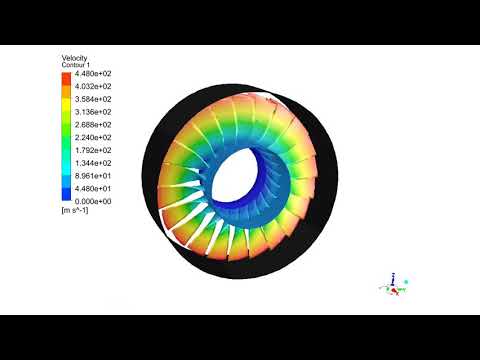
Axial Flow Compressor (Rotor NASA 37) CFD Simulation, ANSYS Fluent Training
The problem is going to simulate the airflow inside an axial flow compressor (Rotor Nasa 37) by ANSYS Fluent software. We perform this CFD project and investigate it by CFD analysis.
The present model consists of a series of blades for an axial flow compressor connected to the central axis within a cylindrical area. To simplify the simulation model, only one row of rotating blades is drawn on the central rotor of the compressor.
The blades rotate around the central axis at a rotational speed of 14043 rpm. In addition, the mass flow rate of the air passing through the compressor is 33.25 kg/s.
The purpose of this project is to investigate the behavior of airflow and the pressure distribution around the blades after compression by the compressor.
The present 3-D model is drawn using SOLIDWORKS software and then imported into the Design Modeler software. The meshing of the present model has been done using ANSYS Meshing software. The mesh type is unstructured and the element number is 278162.
Compressor Methodology
We have used the density-based solver due to compressibility.
To simulate the present model, the Frame Motion technique with the mentioned rotational speed has been used to simulate the airflow in the space around the compressor blades. So the blades are assumed to be fixed (without rotational speed), and the air around the blades has a rotational speed equal to the rotational speed of the compressor rotor.
Also, for the compressor blade wall, the boundary condition of the moving wall with zero rotational speed has been used compared to the surrounding area.
Compressor Conclusion
After the solution process, we obtain the two-dimensional and three-dimensional contours related to pressure, temperature, velocity, and density, as well as the two-dimensional and three-dimensional path lines and velocity vectors in the area for airflow around the compressor blades.
We obtain the two-dimensional contours and pathlines in the YZ section perpendicular to the direction of the compressor axis and in the position of the passage passing through the middle of the blades.
Also, we present pressure, temperature, and heat transfer coefficients on the body of the compressor blades.