

Baffle Cut Effect on Shell and Tube Heat Exchanger
Price: $20
In this project, to investigate conjugated heat transfer, the heat exchanger of shell and tube with metal baffles was modeled.
Baffle Cut Effect on Shell and Tube Heat Exchanger
Price: $20
In this project, to investigate conjugated heat transfer, the heat exchanger of shell and tube with metal baffles was modeled.
Baffle Cut Effect on Shell and Tube Heat Exchanger Efficiency, Conjugated Heat Transfer
Shell and tube heat exchangers are widely used in industry. The use of baffles (usually made of aluminum) and directing the flow of circulating fluid can create more heat distribution inside the shell by its high heat conduction and rise the total heat transfer rate. However, in the meantime, pressure drop should also be considered because enhancing thermal efficiency by increasing the number of baffles will lead to more pressure drop inside the heat exchanger. Therefore, it is necessary to pay attention to baffle cuts and the distance between them in the study of shell and tube heat exchangers.
Problem Description
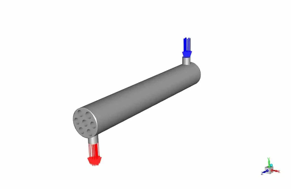
In this project, Baffle Cut Effect on Shell and Tube Heat Exchanger efficiency to investigate conjugated heat transfer, with metal baffles was modeled. ANSYS Fluent software was used for the simulation. At the entrance to the shell, a cooler fluid, assumed to be water, flows at a temperature of 300 K and a flow rate of 0.5 kg / m3 (equivalent to a velocity of 0.7 m / s). The temperature of the inner tubes for cooling purposes was set at a constant wall temperature of 450 K. The material's physical properties are defined as piecewise linear in the software. This study aimed to demonstrate the effect of the high thermal conductivity of baffles on better thermal distribution from hot tubes. The following figure shows the general specifications of the model along with the inlet and outlet of the problem.
Geometry & Mesh
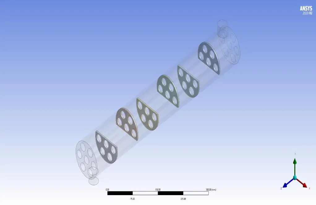
The geometry was designed using the Design modeler module (figure below), and its geometric specifications include a shell with 600 mm distance and 90 mm in diameter, six baffles with a thickness of 4 mm, the center-to-center distance of the baffles was 86 mm, and the value of baffle cut was 36%. Also, seven tubes with an outer diameter of 20 mm with a triangular arrangement and a center-to-center distance were 30 mm inside the shell.
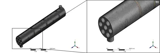
For grid generation, unstructured mesh with 1953754 elements and 30 mm element size in the ANSYS Meshing module was used. In addition, a boundary layer mesh was used near the walls to satisfy the Y-Plus number condition of the standard wall function. The following figure shows the mesh at different magnifications.
Baffle Cut Effect on Shell and Tube Heat Exchanger CFD Simulation Solver Setting
Fluent software was used to solve the governing equations numerically. Then, the problem is analyzed steadily, using the pressure-based method and considering the gravitational effects.
Material Properties
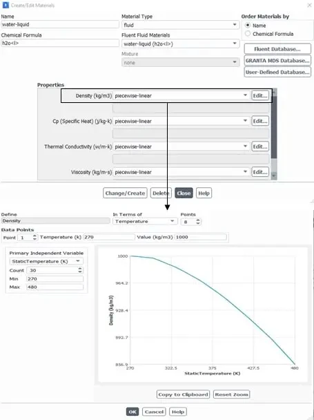
In this study, water fluid was used as the working fluid. Since the properties of water are defined as constants in the Fluent database, to improve the accuracy, they are redefined using piecewise-linear functions of temperature by using the ‘‘Thermo-Physical Properties of Saturated Water” tables available in the Thermodynamic books.
Boundary conditions & Solution methods for Baffle Cut Effect on Shell and Tube Heat Exchanger
Also, The table below shows the characteristics and values of boundary conditions, along with the models and hypotheses.
| Material Properties | |||
| Amount | Fluid properties (water) | ||
| piecewise linear | Density | ||
| piecewise linear | Specific heat | ||
| piecewise linear | Thermal conductivity | ||
| piecewise linear | viscosity | ||
| Boundary Condition | |||
| Type | Amount (units) | ||
| Mass flow inlet (water at 300 K) | 0.5 kg/m3 | ||
| pressure outlet (gauge pressure) | 0 pa | ||
| Shell wall | Adiabatic (heat flux=0 W/m2) | ||
| Tube wall | Constant temperature (450 K) | ||
| Cell zone condition | |||
| solid | fluid | ||
| baffles | water | ||
| Turbulence models (Shell&Tube) | |||
| K- | viscous model | ||
| realizable | K- model | ||
| Standard wall | Wall function | ||
| Solution methods ( Shell&Tube ) | |||
| Simple | pressure velocity coupling | ||
| standard | pressure | spatial discretization | |
| First-order upwind | momentum | ||
| First-order upwind | turbulent kinetic energy | ||
| First-order upwind | turbulent dissipation rate | ||
| First-order upwind | energy | ||
| Initialization | |||
| standard | initialization method | ||
| 0 (Pa) | gauge pressure | ||
| -0.7 m/s | y-velocity | ||
| 0 (m/s) | y-velocity, z-velocity | ||
Results
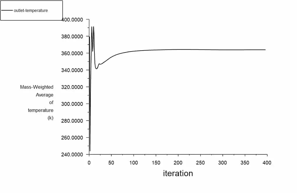
In this section, by examining the outlet temperature diagram of the shell, which is around 360 K, considering that the inlet temperature was 300 K, with the passage of hot fluid through the pipes, the water temperature increases by moving between the pipes.
Also, the values of heat transfer coefficient and total heat transfer rate converge with increasing iteration.
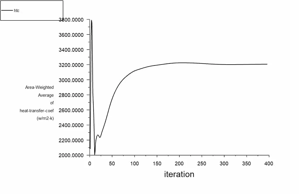
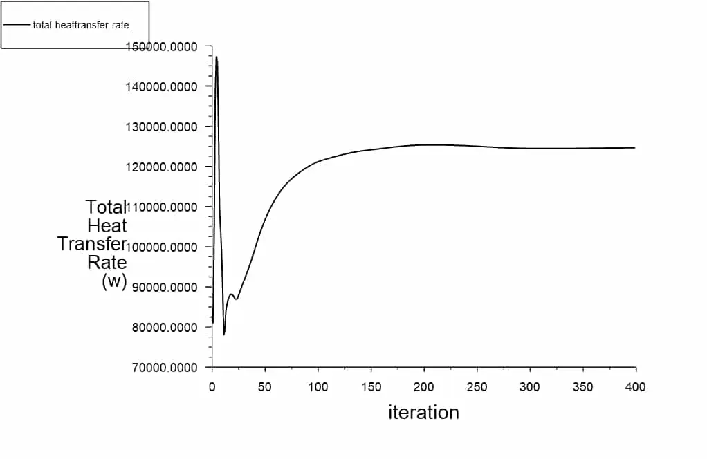
As can be seen in the results, by simultaneously modeling the baffles and the fluid flow and studying the problem from the perspective of conjugated heat transfer, it was found that temperature diffusion occurs much more quickly due to the presence of baffles, and this increases the average temperature of the fluid as much as possible. It is also proportional to the increase in heat transfer coefficient.
In addition, the total pressure contour at a plain in the middle of the heat exchanger shows that the amount of pressure drop is in the range of 1 kPa for this exchanger.