

Brake Disk System Conduction Heat Transfer, ANSYS Fluent Simulation Training
Price: $210
In this project, the heat conduction of a brake disk system is modeled and simulated.
Brake Disk System Conduction Heat Transfer, ANSYS Fluent Simulation Training
Price: $210
In this project, the heat conduction of a brake disk system is modeled and simulated.

Brake Introduction
Brake is among the most widespread units with the non-stationary friction. We use braking friction systems for damping the kinetic energy of the rotational or translational motion of masses by friction forces. By braking, one can decrease the velocity of relative sliding to zero or the given value. In the course of operation of braking units, parameters like velocity, temperature, friction-wearing characteristics of materials vary greatly.
Project description
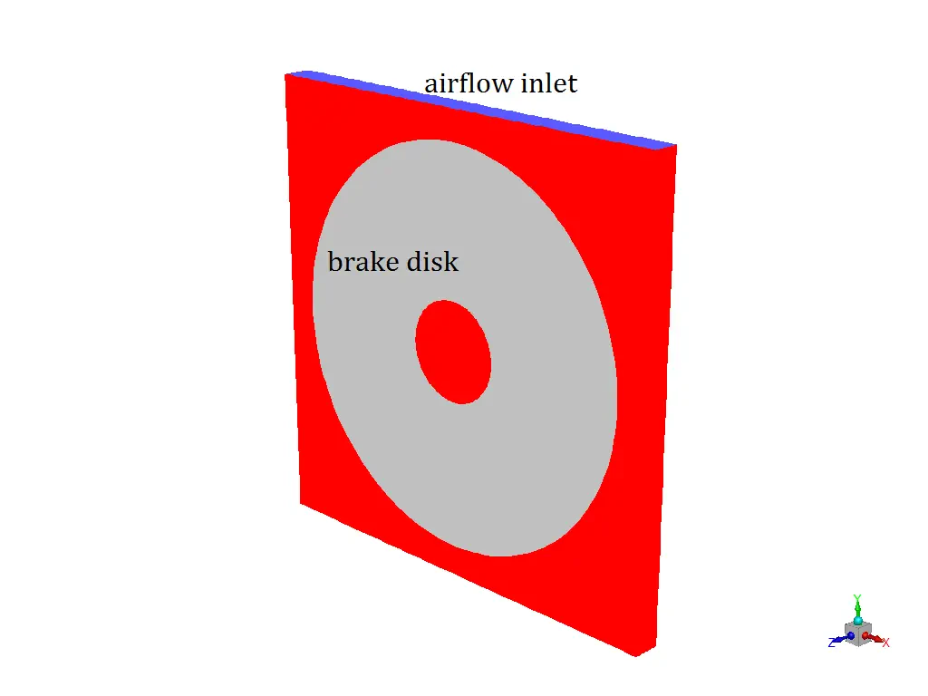
In this project, the heat conduction of a brake disk system is modeled and simulated by ANSYS Fluent. The disk revolves with the speed of 20rad/s and a braking pad is set to make contact with the disk. This frictional contact will result in heat generation inside the disk and the pad. The heat produced in the contact region will be dissipated based on heat conduction formula. Energy and laminar model is activated. Also, MRF model (frame motion) is activated to model the rotational motion of the disk. A UDF is implemented to account for the radial heat flux.
Brake Geometry and mesh
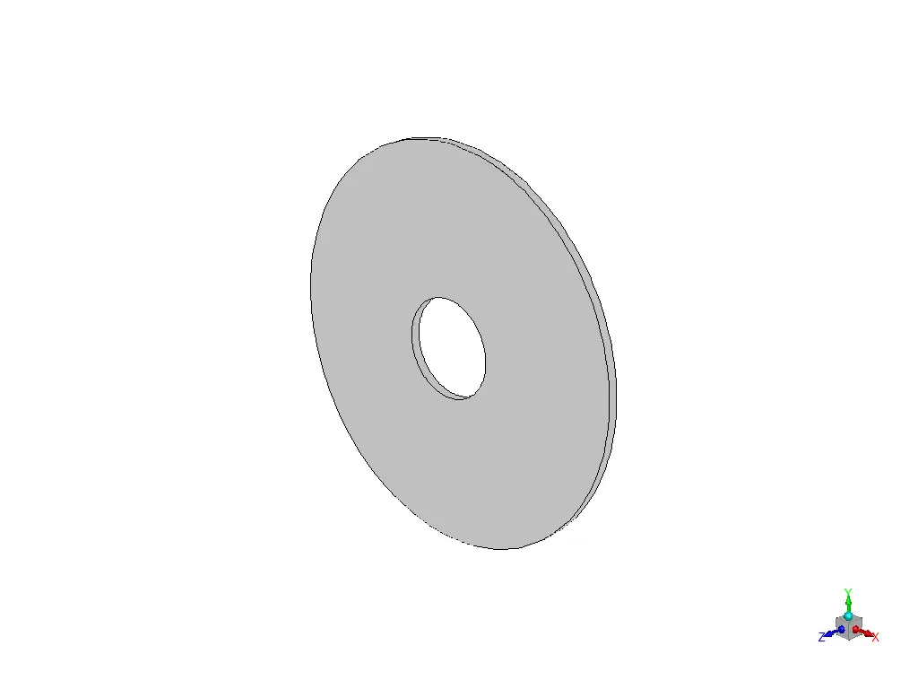
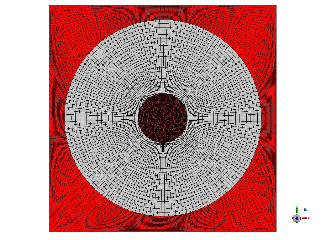
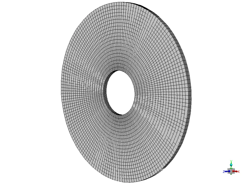
The modeled geometry for this simulation consists of a brake disk and a pad and a fluid flow domain. We design and mesh it inside Gambit®. The mesh type used for this geometry consists of both types of structured and unstructured (hybrid) and the element number is 198594.
Brake CFD Simulation Settings
The key assumptions considered in this project are:
- Simulation is done using pressure-based solver.
- The present simulation and its results are considered to be steady and do not change as a function time.
- The effect of gravity has not been taken into account.
The applied settings are summarized in the following table.
| (brake) | Models | |
| Viscous model | Laminar | |
| Energy model | Activated | |
| Cell zone conditions | ||
| Solid | ||
| MRF | Rotational velocity | 20 rad/s |
| Boundary conditions | ||
| Inlets | velocity inlet | |
| airflow | 10 m/s | |
| Temperature | 300 K | |
| Outlets | outflow | |
| Walls | ||
| wall motion | stationary wall | |
| (brake) | Solution Methods | |
| Pressure-velocity coupling | Simple | |
| Spatial discretization | pressure | standard |
| energy | first order upwind | |
| momentum | first order upwind | |
| Initialization | ||
| Initialization method | Standard | |
| gauge pressure | 0 Pa | |
| velocity (x,y,z) | (0,0, 0) m/s | |
| Temperature | 300 K | |
Results
At the end of the solution, we present the contours of temperature, surface heat flux, surface Nusselt number, surface enthalpy and flow streamlines around the brake disk.