

Centrifuge CFD Simulation, Two-Phase Flow (MIXTURE), ANSYS Fluent
Price: $14
In this project, the effect of the steady rotation of a centrifugal turbine on a water and air two-phase mixture is investigated.
Centrifuge CFD Simulation, Two-Phase Flow (MIXTURE), ANSYS Fluent
Price: $14
In this project, the effect of the steady rotation of a centrifugal turbine on a water and air two-phase mixture is investigated.
Centrifuge Problem description
In this project, the effect of steady rotation of a centrifugal turbine on a water and air two-phase mixture is investigated by ANSYS Fluent software. Multi-phase MIXTURE model is used to solve water and air phase interactions. The secondary phase (air) volume fraction has very low values in the 0.0001 order, which proves the validity of the mixture multi-phase model in this project, since for applying the Mixture Multi-Phase model, the secondary phase volume fraction should be less than 15%. Slip velocity has been taken into account at the water and air contact interface. The diameter of air bubbles is considered equal to 1 µm. The rotating region of the turbine is considered a separate body that rotates with a rotational speed equal to 500 rpm, which simulates the rotation of the centrifugal turbine at the same rate. Frame Motion (MRF) model has been applied for the rotation simulation.
Centrifuge Geometry and mesh
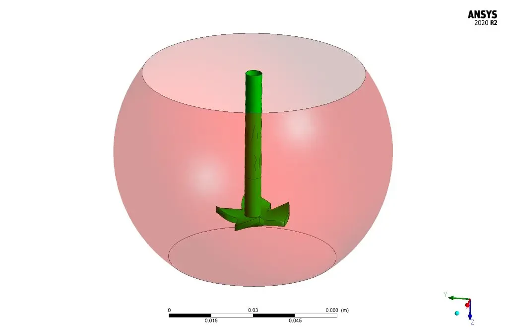
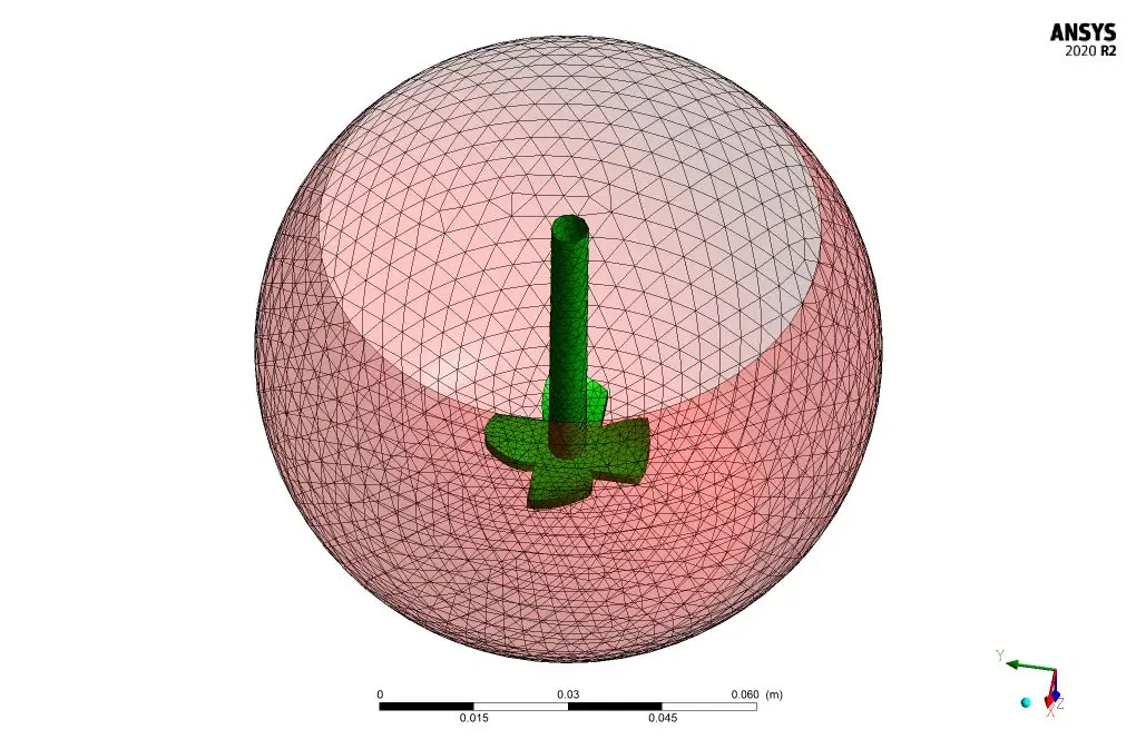
The geometry of the fluid domain is designed in the Design modeler and the computational grid is generated using Ansys meshing. The mesh type is unstructured, and the element number is 126000.
Solver Configuration for Centrifuge CFD Simulation
Critical assumptions:
- Solver type is assumed Pressure Based.
- Time formulation is assumed to be Steady.
- Gravity effects are considered in a positive Z direction equal to 9.84 m/s2.
The following table a summary of the defining steps of the problem and its solution.
| Models (Centrifugal Turbine) | ||
| Multiphase | Model | Mixture |
| Slip velocity | Activated | |
| Number of Eulerian phases | Two | |
| Volume fraction parameters | Implicit | |
| Interface modeling | Dispersed | |
| Primary phase | Water | |
| Secondary phase | air | |
| Phase interaction | Drag (schiller-naumann) | |
| Slip velocity | Manninen et al. | |
| Viscous | k-epsilon | RNG |
| RNG option | Swirl dominated flow | |
| Near wall treatment | Standard wall function | |
| Materials (Centrifugal Turbine) | ||
| Air | Definition method | Fluent Database |
| Material name | Air | |
| Density | 1.225 kg/m3 | |
| Viscosity | 1.7894e-05 kg/m.s | |
| Water | Definition method | Fluent Database |
| Material name | Water | |
| Density | 998.2 kg/m3 | |
| Viscosity | 0.001003 kg/m.s | |
| Cell zone conditions (Centrifugal Turbine) | ||
| Turbine | Material name | mixture |
| Frame motion | On | |
| Rotational velocity | 500 rpm | |
| Boundary conditions (Centrifugal Turbine) | ||
| Outlet | Type | Pressure outlet |
| Gauge pressure | 0 atm | |
| Solver configurations (Centrifugal Turbine) | ||
| Pressure-velocity coupling | Scheme | SIMPLE |
| Spatial discretization | Gradient | Least square cell-based |
| Pressure | PRESTO! | |
| Momentum | First order Upwind | |
| Volume fraction | First order Upwind | |
| Turbulent kinetic energy | First order Upwind | |
| Turbulent dissipation energy | First order Upwind | |
| Initialization | Gauge pressure | 0 Pa |
| X velocity | 0 m/s | |
| Y velocity | 0 m/s | |
| Z velocity | 0 m/s | |
| Turbulent kinetic energy | 1 m2/s2 | |
| Turbulent dissipation rate | 1 m2/s3 | |
Results and discussion
Rotation of the centrifugal turbine with the rotational speed of 500 rpm results in fluid movement with a velocity equal to 0.62 m/s at close ranges of the turbine. Water bubbles are captured under the turbine which increases the secondary phase (air) volume fraction in these regions.