

Circulating Fluidized Bed (CFB) Gasifier, CFD Simulation ANSYS Fluent Training
Price: $390
- This project involves the simulation of air and biomass combustion in a Circulating Fluidized Bed (CBF) using CFD techniques.
- The primary objectives are to examine the combustion characteristics of Probability Density Function (PDF) for biomass combustion simulation.
- The CFB is defined with specific boundary conditions, and simulations are performed using a steady-state for fluid flow, unsteady for DPM, and incompressible flow model.
- The turbulent flow within the CFB is modeled using the realizable k-e turbulent model and thermal radiation is simulated with the P1 model.
- The simulation incorporates the single rate model for devolatilization of biomass and the intrinsic model for particle combustion.
Circulating Fluidized Bed Project Description
the Circulating Fluidized Bed gasifier is popular in industrial applications and academic studies because of its intrinsic advantages in high circulating rate, low operating temperature, broad fuel flexibility, and negligible pollutant emissions. In this simulation, a simple gasification (CFB cycle) has been simulated, and results obtained.
The system consists of two inlets, a vertical inlet for oxidizer and a horizontal inlet for fuel; the air and fuel, after mixed, start flameless combustion in a vertical section and then enter the cyclone to separate unburned ashes as polluted air, unburn fuel circulates to bottom of the downstream section and enters the process again and heavy sands and ashes exit from the bottom outlet. The Probability Density Function (PDF) has been used in this simulation to simulate solid dynamics.
Geometry & Mesh
The 3-D domain of this simulation has been designed in ANSYS Design Modeler.
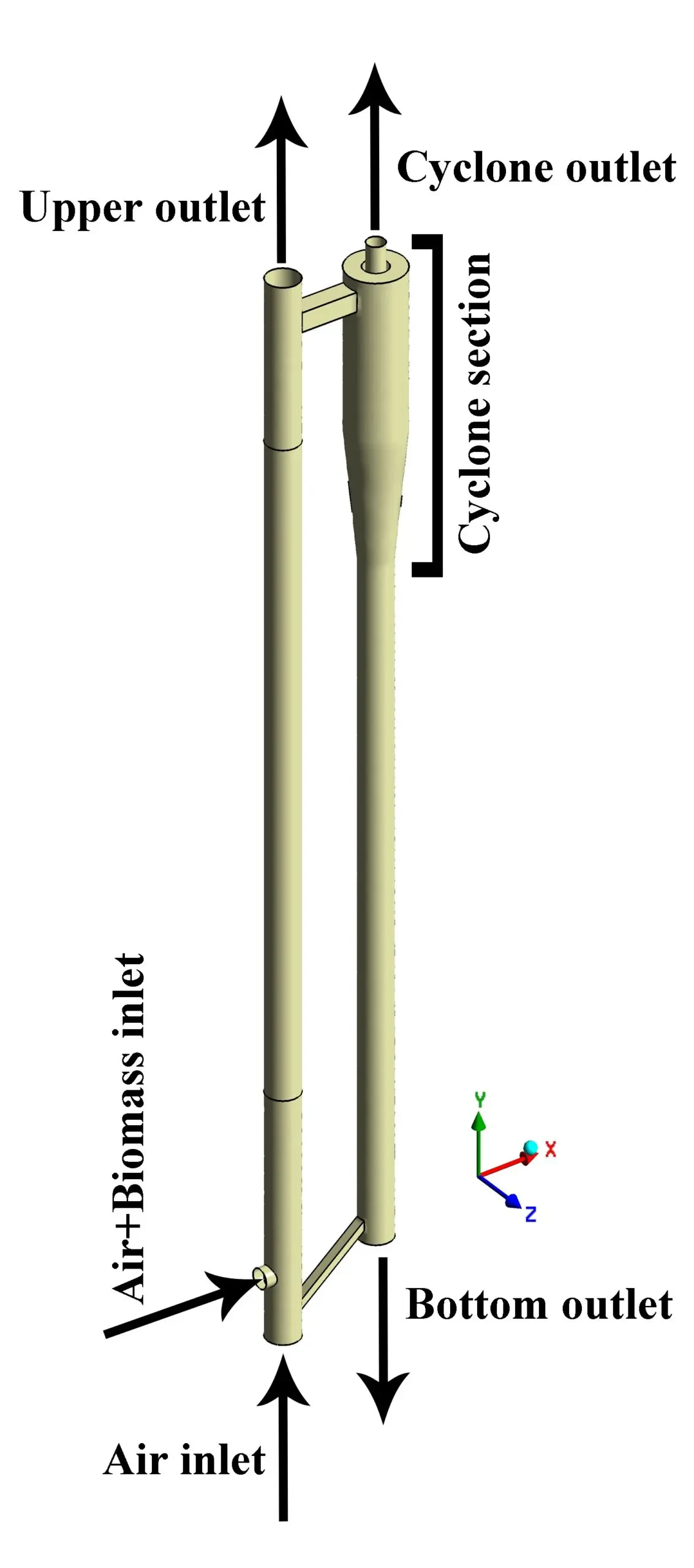
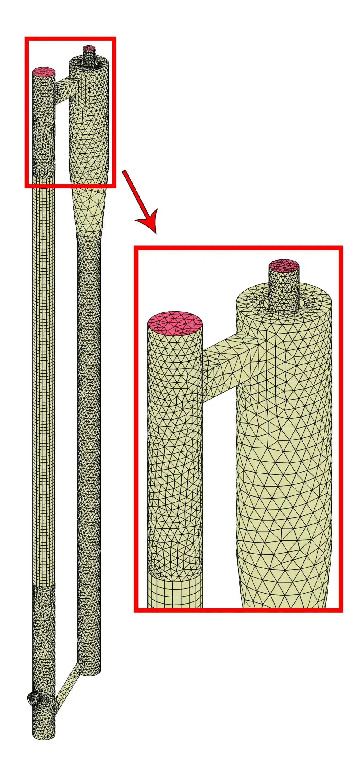
The meshing of this present model has been generated by ANSYS Meshing software. The mesh grid is unstructured, and the total cell number is 88477 elements. The figure below shows an overview of the performed mesh.
CFD Simulation
To simulate the present model, several assumptions are considered, which are:
- The solver is pressure-based.
- The effect of gravity on the flow has been considered
- The hot zone wall model is considered a heat flux
The following is a summary of the steps for defining the problem and its solution.
| Models | ||
| k-epsilon | Viscous model | |
| Standard wall function | Near -Wall treatment | |
| Pressure based | Solver | |
| steady | Timestep | |
| Non – premixed combustion | Species model | |
| Chemical equilibrium | State relation | |
| Non-adiabatic | Energy treatment | |
| P1 | Radiation model | |
| On | Discrete phase model | |
| Unsteady particle tracking | Particle treatment | |
| Combusting | Injection type | |
| On | Energy | |
| Boundary conditions | ||
| Velocity-inlet | Air inlet | |
| 18 m/s | Fluid inlet velocity | |
| 300 k | Temperature | |
| 1 | Internal emissivity | |
| 0 | Soot mass fraction | |
| 0 | Mean mixture fraction | |
| 0 | Mixture fraction variance | |
| Escape | Discrete phase BC type | |
| Velocity inlet | Bio inlet | |
| 15 m/s | Particle inlet velocity | |
| 330 k | Temperature | |
| 1 | Internal emissivity | |
| 0 | Soot mass fraction | |
| 1 | Mean mixture fraction | |
| 0 | Mixture fraction variance | |
| Escape | Discrete phase BC type | |
| Pressure outlet | Cyclone outlet | |
| 0 | Supersonic gage pressure | |
| Pressure outlet | Qr outlet | |
| -120w | heat flux | |
| wall | Q2 wall | |
| stationary wall | wall motion | |
| heat flux | Thermal condition | |
| 250 w | heat flux | |
| wall | wall | |
| stationary wall | wall motion | |
| Non | Thermal condition | |
Circulating Fluidized Bed Results
The simulation results show that the ignition of the fuel-air mixture in the vertical chamber and the hot gases resulting from the ignition is cooled in the cyclone and the second chamber, and the polluting gases of the maximum face are also examined. Unburned materials are separated inside the cyclone and re-entered the combustion process.
The counter below shows pressure, temperature, and gas volume fraction.