

Compound Channel with Non-Prismatic Floodplain Simulation, Paper Numerical Validation
Price: $27
The present problem simulates a two-phase flow within a compound channel using ANSYS Fluent software. This simulation is based on the information from a reference article, "Application of the Shiono and Knight Method in compound channels with non-prismatic floodplains," and its results are compared and validated with the results in the article.
Paper Description
The problem simulates a two-phase flow within a compound channel using ANSYS Fluent software. This simulation is based on the information from a reference article, "Application of the Shiono and Knight Method in compound channels with non-prismatic floodplains," and we compare and validate its results with the results in the article. Most natural waterways (floodplains) consist of the main channel through which the natural flow of water moves. However, when the water flow increases, one or more flood layers are created in this main channel's vicinity as a floodplain. Therefore, we can assume a channel whose cross-section does not consist of a basic geometric shape in this case.
These types of channels are called compound channels. The present simulation aims to investigate two-phase flow behavior, including water and air, in a compound channel. The compound channel geometry is based on the data in Figure 1-c of the reference paper. Since the present model consists of two phases of air and water, we use the multiphase Volume of Fluid model (VOF) in the Fluent software; So that the amount of surface tension force between the air and water is defined as 0.072 N.m-1. Also, since the water flow at the inlet section of the canal is only up to a certain height or level, the open channel flow model should be used. Thus, the height of the water level at the inlet section is equal to 0.0357143 m.
The water flow enters the channel at the inlet section with a flow rate of 17.9676 kg.s-1 (equivalent to a volume flow rate of 18 L.s-1); While the airflow in the inlet section is static and defined with zero mass flow rate.
Compound Channel Geometry & Mesh
The present model is designed in three dimensions using Design Modeler software. These models are related to a convergent compound channel. The drawn model's geometric characteristics are associated with the article's third geometric design (Figure 1-c). This channel's length equals 17 m and has a height or depth equal to 0.15 m. Also, since the channel is converging, its cross-sectional width at the channel's entrance is equivalent to 1.198 m, and at the channel's exit, it is equal to 0.798 m. Meanwhile, the canal's main part in the canal route has a width of 0.398 m and a depth of 0.025 m.
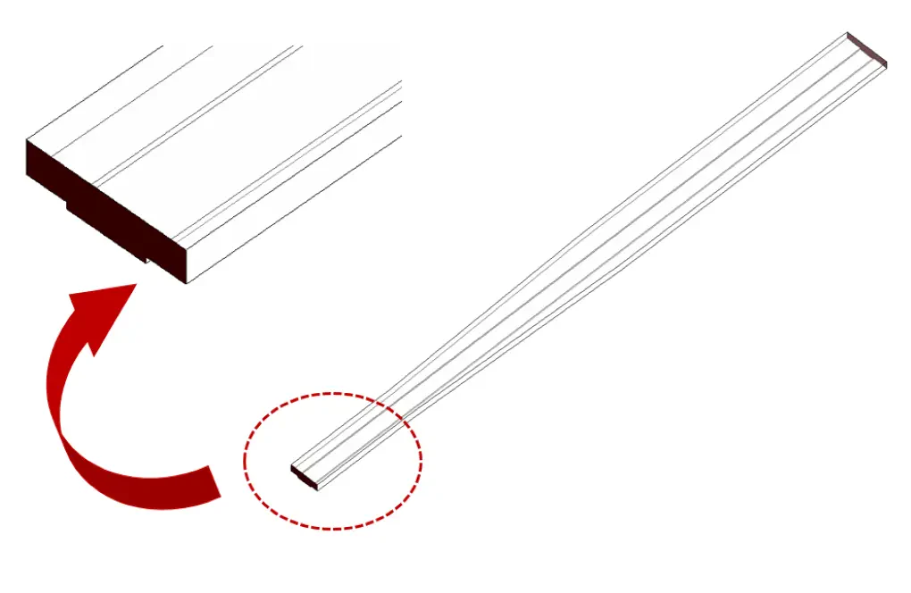
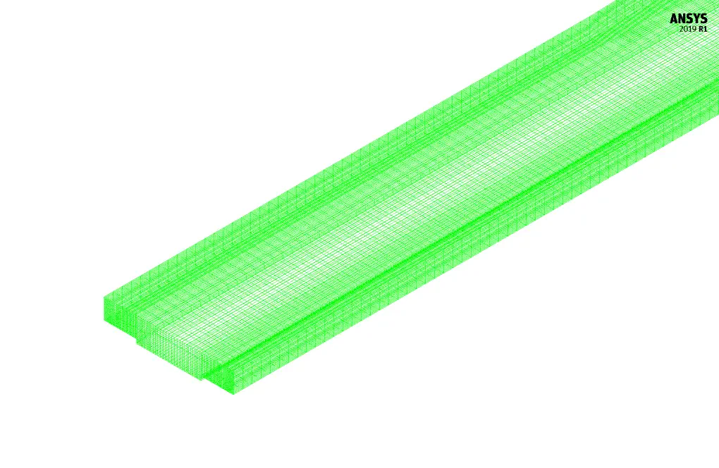
We carry out the meshing of the model using ANSYS Meshing software, and the mesh type is structured. The element number is 540000. The following figure shows the mesh.
Compound Channel CFD Simulation
We consider several assumptions to simulate the present model:
- We perform a pressure-based solver.
- The simulation is steady.
- The gravity effect on the fluid is equal to -9.81 m.s-2 along the Y-axis.
The following table represents a summary of the defining steps of the problem and its solution:
| Models | ||
| Viscous | k-epsilon | |
| k-epsilon model | standard | |
| near wall treatment | standard wall function | |
| Multiphase Model | VOF | |
| number of Eulerian phases | 2 (air & water) | |
| formulation | implicit | |
| interface modeling | sharp | |
| Boundary conditions | ||
| Inlet | Mass Flow Inlet | |
| free surface level for water | 0.0357143 m | |
| mass flow rate for water | 17.9676 kg.s-1 | |
| mass flow rate for air | 0 kg.s-1 | |
| Outlet | Pressure Outlet | |
| gauge pressure | 0 pascal | |
| Walls | Wall | |
| wall motion | stationary wall | |
| Methods | ||
| Pressure-Velocity Coupling | coupled | |
| pressure | body force weighted | |
| momentum | first order upwind | |
| volume fraction | Modified HRIC | |
| turbulent kinetic energy | first order upwind | |
| turbulent dissipation rate | first order upwind | |
| Initialization | ||
| Initialization methods | Hybrid | |
Results & Paper Validation
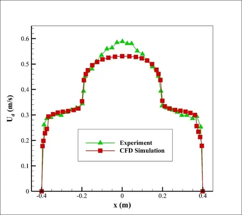
The present paper validation is based on the diagram in Figure 10-a of the mentioned article. This diagram is related to the profile of velocity value changes along the channel cross-section. This profile was obtained at a distance of 14 m from the channel entrance. Also, changes in the vertical velocity of the mixed flow and the line corresponding to the interface surface between the two water and air phases have been obtained.
The iso-surface command can create a plane in which the volume fraction of water or air is 0.5 to find the line corresponding to the interface between the two phases because it can be assumed that the volume fraction of each of the two phases at the interface between the two phases is approximately equal to 0.5. Comparison and validation of the present numerical work results with the results of experimental work in the article are shown in Figure 3. These diagrams show that the amount of velocity in the space above the central part of the compound channel is higher than at other points.
At the end of the solution process, two-dimensional contours related to the pressure, velocity, and volume fraction of each air and water phase are obtained. Two-dimensional contours are obtained in a section parallel to the channel inlet section (X-Y plane) and at a distance of 14 m from it.