

Conjugated Heat Transfer (CHT) with Viscous Heating, CFD Simulation with Ansys Fluent
Price: $10
In this project, Conjugated Heat Transfer (CHT) with Viscous Heating has been simulated and the results of this simulation have been investigated.
Conjugated Heat Transfer (CHT) with Viscous Heating, CFD Simulation with Ansys Fluent
Price: $10
In this project, Conjugated Heat Transfer (CHT) with Viscous Heating has been simulated and the results of this simulation have been investigated.
CHT Introduction
conjugate heat transfer (CHT) analysis can precisely simulate heat transfer by simultaneously solving solid and flow field heat transfer processes. CHT in CFD allows for the heat transfer simulation between Solid and Fluid domains by exchanging thermal energy at the interfaces between them. For example, conduction in solid and free and forced convection in fluid and even radiation between them.
In the default state in Ansys Fluent, The viscous heating terms in the energy equation are ignored when the pressure-based solver is used, but They are always On for the density-based solver. Viscous dissipation term should be enabled when the shear stress in the fluid is significant, or the velocity of the fluid is high, and when there are compressible flows in the domain.
Viscous heating arises as a consequence of fluid deformation, which causes shear within it. Momentum is then diffused down the velocity gradient. In another view, viscous heating represents the effect of a process in which a fluid works on head-to-head layers due to shear forces and is converted into heat.
Conjugated Heat Transfer (CHT) with Viscous Heating Project Description
In this project, Conjugated Heat Transfer (CHT) with Viscous Heating in a solid domain consisting of 3 channels inside, flowing into the domain on one side and leaving it on another side, is investigated. The channels with a square cross-section are located at an equivalent distance, while the central channel is in the body's center. There is a high-velocity flow, and very small cross-section area channels are set in the domain in order to intensify viscous heating and see it clearly in results.
Energy is transferred from the channels' boundaries, enters into the solid domain, and moves forward due to conduction of the solid body, which is set as Aluminum. There is another convection effect from the free stream flowing around the domain, cooling down the body. The temperature of the fluid in channels and solid body are equal to 300 K, and viscous heating is the only phenomenon that generates heat while the free stream air is cooling the domain.
Geometry & Mesh
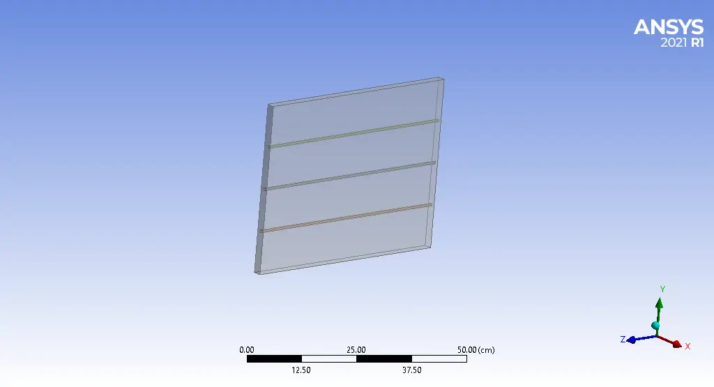
The geometry of the solution is a 3D cubic domain with 2, 40, and 50 cm in X, Y, and Z directions, respectively. The square cross-section of channels has 5mm edge sizes. Design Modeler software is used to create the geometry of the solution. All four bodies created in software are set as one part, so the interfaces are Coupled.
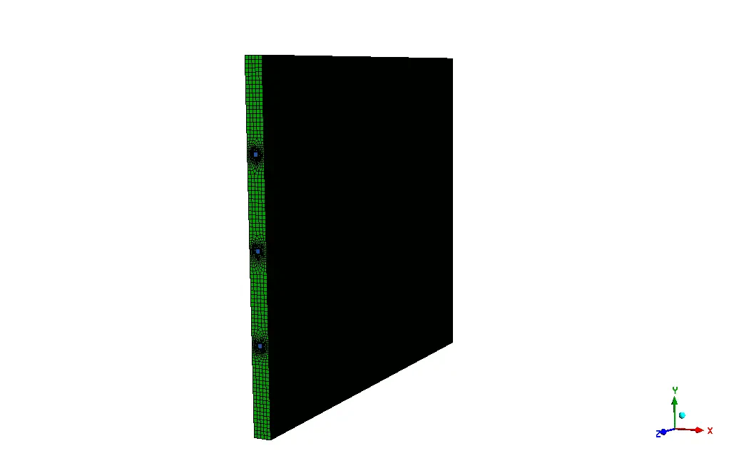
Ansys meshing software is used for generating meshes of the solution. The elements are in the Automatic selection state (Unstructured), and the number of them is precisely 1695376.
CHT CFD Simulation
We consider several assumptions to simulate the present model:
- We perform a pressure-based solver.
- The energy equation is On.
- The present model is steady.
- The effect of gravity due to the high velocity of the flow is neglected.
The following table represents a summary of the defining steps of the problem and its solution:
| Material Properties | |
| Name (Fluid) | Water-liquid |
| 998.2 | Density |
| 4182 | Specific heat |
| 0.6 | Thermal conductivity |
| 0.001003 | viscosity |
| Name (Solid) | Aluminum |
| 2719 | Density |
| 871 | Specific heat |
| 202.4 | Thermal conductivity |
| Boundary Condition | |
| Type | Amount (units) |
| Velocity inlet | 10 m/s |
| Outer wall | Convection, heat transfer coefficient = 5 W/(m2k) Free stream temperature = 293 k |
| pressure outlet (gauge pressure) | 0 pa |
| Cell zone condition | |
| solid | fluid |
| Body_Zone | Upper_Flow, Middle_Flow, Bottom_Flow |
| Models | |||
| Energy | On | ||
| Turbulence models | |||
| K-Omega | viscous model | ||
| SST | K-Omega model | ||
| Viscous Heating, Corner Flow Correction, Production Limiter | Options | ||
| Solution methods | ||
| Coupled | pressure velocity coupling | |
| Standard | pressure | spatial discretization |
| Second-order upwind | momentum | |
| Second-order upwind | turbulent kinetic energy | |
| Second-order upwind | Specific dissipation rate | |
| Second-order upwind | energy | |
| Initialization | ||
| standard | initialization method | |
| Middle inlet | Compute from | |
| 0 (Pa) | gauge pressure | |
| 0 (m/s) | y-velocity | |
| 0 (m/s) | x-velocity | |
| 10 (m/s) | z-velocity | |
| 0.375 | Turbulent Kinetic Energy | |
| 37320.54 | Specific dissipation rate | |
| 300 K | Temperature |
Results
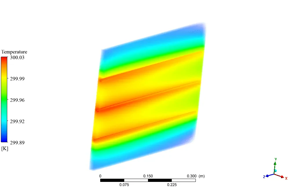
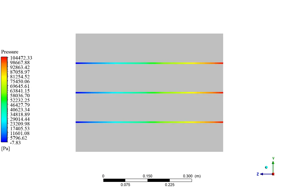
At the end of the solution process, two and three-dimensional contours and vectors related to water pressure, temperature, and velocity are obtained. At first, water flow enters the inlet face and moves to the outlet face at high speed. As can be seen in the pictures, heat transfer on the interface of the bodies increases as water flows through the channel, and then the energy moves forward due to the conduction of the solid body. Also, fluid enters the channel in a high-pressure value and leaves it with a gauge pressure equal to 0.
You can obtain Geometry & Mesh file and a comprehensive Training Movie that presents how to solve the problem and extract all desired results.