

Contra-Rotating Turbine CFD Simulation Training
Price: $42
- In this project, a flow around a Contra-Rotating Turbine has been simulated, and the results of this simulation have been investigated.
- This ANSYS Fluent CFD training simulates a contra-rotating VAWT turbine with two blade rows rotating oppositely at 14.7 rad/s.
- Inlet velocity is 5.3 m/s; mesh motion defines rotations using k-epsilon model and steady pressure-based solver.
- Results show enhanced pressure/velocity between blades, doubling torque (~1.9 N.m per row) for better power.
Contra-Rotating Turbine, Ansys Fluent CFD Simulation Training
The present simulation is about a contra-rotating VAWT turbine via ANSYS Fluent. The contra-rotating turbine is an axial flow turbine with two rows of blades, So these two rows of blades rotate with equal rotational speed but in opposite directions. Contra-rotating turbines recover energy and power loss due to airflow through the front row of blades.
In other words, using two rows of rotating blades in opposite directions doubles the turbine's torque power.
In this simulation, the mesh motion method defines the rotational motion of air.
In this model, two rows of blades are designed. A distinct zone for airflow is defined in the vicinity of each of these rows. Then, for each of these two zones, mesh motion is used. The rotational velocity of both rows of blades is defined as 14.7 rad.s-1; But these two areas' central axis of rotation is defined in opposite directions.
The airflow around the upper blades rotates clockwise, and the lower row blades rotate counterclockwise. Also, the inlet airflow velocity to the computational domain is defined as 5.3 m.s-1.
Geometry & Mesh
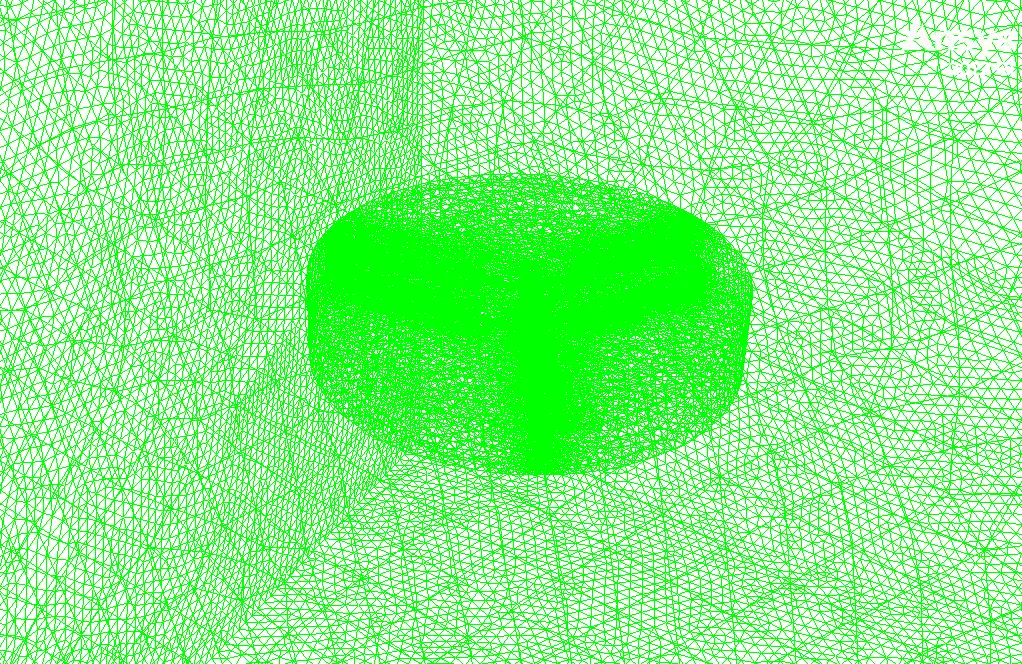
The present geometry is designed in a 3D model via Design Modeler. This model includes a rectangular cube computational domain with two rows of blades connected in parallel in the middle. Each row of blades has three blades. The mesh of the present model has been done via ANSYS Meshing. Mesh is done unstructured, and the number of production cells is equal to 3747546.
Set-up & Solution
This steady-state simulation utilizes a pressure-based solver while neglecting gravity effects. The viscous model employs the standard k-epsilon turbulence formulation with standard wall functions for near-wall treatment. Boundary conditions include a velocity inlet with 5.3 m/s magnitude, stationary walls for the up and down blades, a pressure outlet at 0 Pa gauge pressure, and symmetry boundaries. The solution employs SIMPLE pressure-velocity coupling with standard initialization.
Contra-Rotating Turbine Results
After simulation, streamlines and 2D contours related to velocity, pressure, and velocity and pressure gradients are obtained. The contours show that pressure and velocity in the space between the two rows of turbine blades increase, and, as a result, the value of torque and power applied to the turbine blades is enhanced.
Also, the value of torque applied to the upper blades (clockwise) is equal to 1.89 N.m, and the value of torque applied to the lower blades (counterclockwise) is equal to 1.93 N.m. Therefore, in this turbine model, approximately equal torque is applied to each row of blades.