

Dimpled Cylinder Flow Control, Paper Numerical Validation, ANSYS Fluent Training
Price: Free
- The problem numerically simulates the water flow around a dimpled cylindrical body using ANSYS Fluent software.
- We design the 3-D model with the Design Modeler software.
- We Mesh the model with ANSYS Meshing software.
- The mesh type is Structured, and the element number equals 1966490.
- This project is simulated and validated with a reference article.
- We aim to investigate the drag and lift forces.
Description
The present problem simulates the water flow inside a rectangular computational domain around a dimpled cylindrical body (protrusion) on its inner surface by ANSYS Fluent software.
The results of this simulation have been compared and validated with the results in the article "Control of flow past a dimpled circular cylinder".
The fluid used in the model is water. The Reynolds number used for the fluid flow is 17980, which according to the formula for the Reynolds number, the inlet flow velocity is 0.45 m/s.
The cylindrical body is vertical and located in the direction of fluid flow within the computational domain, where the incoming water flow hits the body of its lateral surface horizontally.
As mentioned, several dimples are placed on the inner surface of this hollow cylinder; These dimples create a bulge on the inner surface and a depression on the outer surface of the cylinder.
Several patterns have been considered in the reference paper to place dimples on the cylindrical surface. In the present work, the DF (dimple full) type pattern has been used, Which means that the dimples fill the surfaces.
The geometry of the present model is drawn in three dimensions using SOLIDWORKS software. The geometry consists of a channel with a rectangular cross-section in which a hollow cylindrical body is located vertically. Dimples or bumps are also created on the inner surface of the cylinder.
These dimples are placed all over the entire body of the cylindrical body. The computational space of a rectangular cube is 6 m * 0.3 m * 0.4 m, and the cylinder has a length of 0.4 m and a diameter of 0.04 m.
The meshing has been done using ANSYS Meshing software, and the mesh type is Structured. The element number is 1966490.
Methodology
The main purpose of this work is to investigate the aerodynamic forces, including drag and lift force, on the cylinder's outer surface and calculate drag and lift coefficients.
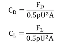
To calculate the drag coefficient and lift coefficient, the following equations are used, where ρ represents the fluid density, U represents the free flow velocity, and A represents the surface area that faces the fluid flow (0.4 * 0.04 = 0.016):
The simulation was performed as steady-state and transient, and the aerodynamic forces were obtained. In the transient mode, for the 60s with a time step size equal to 1s. The results showed that the changes of these aerodynamic forces in the unsteady state also become stable after a short time.
Conclusion
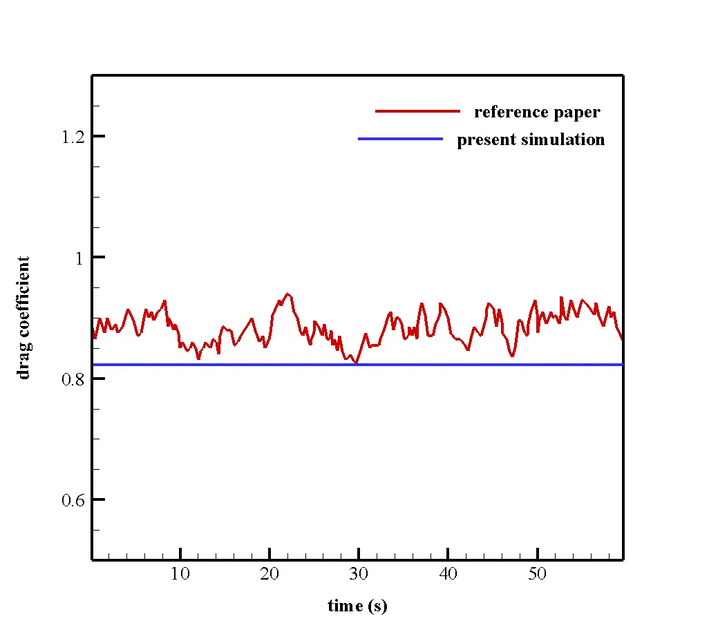
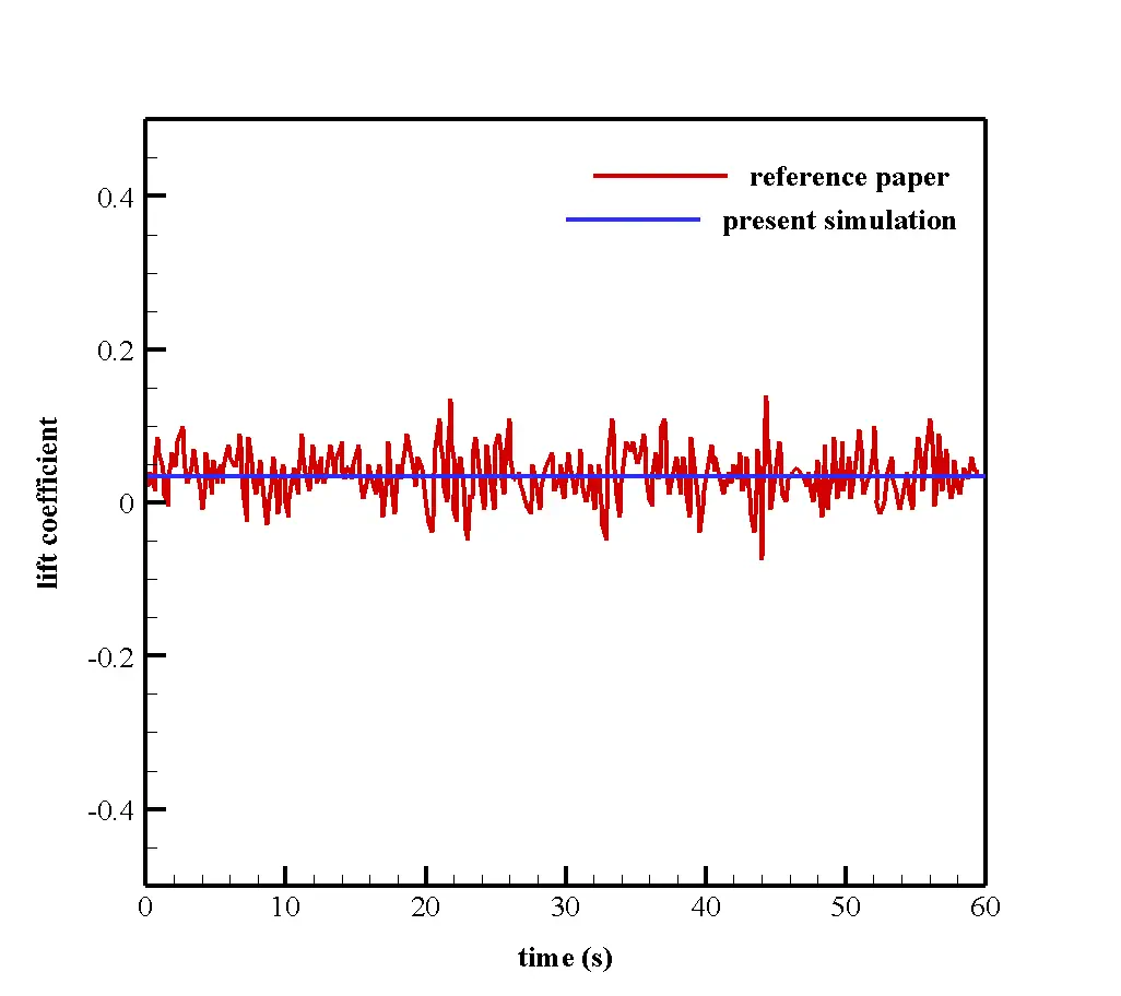
At the end of the solution process, we obtain the drag and lift coefficient diagram in both steady and transient modes over 60 s by taking a time step size equal to 1 s.
As the results show in the transient state, these coefficients reach an almost constant value after some time. We compare and validate these two graphs with their related graphs in the article. For this purpose, we use the DF mode in Figure 4 of the article. The following figures show the comparison and validation of the graphs.
The dimples are also modeled so that the diameter of each dimple to the diameter of the cylinder is equal to 0.1, and the depth of each dimple to the diameter of the cylinder is equal to 0.05.
At the end of the simulation, we obtain and analyze two-dimensional contours related to pressure, velocity, and velocity vectors. We draw two-dimensional contours in the X-Y section on a plane perpendicular to the body of cylindrical shapes passing through the center of this cylinder.