Elbow Optimization with RBF Morph, CFD Simulation Ansys Fluent Training
Price: $180
In this project, an elbow optimized with the RBF (Mesh Morphing) Method and the results of this simulation has been investigated.
Elbow Optimization with RBF Morph, CFD Simulation Ansys Fluent Training
Price: $180
In this project, an elbow optimized with the RBF (Mesh Morphing) Method and the results of this simulation has been investigated.
Introduction to RBF Morph (Mesh Morphing)
Today, geometry optimization methods have been greatly developed to achieve better performance in mechanical devices. One of these methods is mesh morphing (RBF). Mesh morphing is a method of reshaping the lattice surface while preserving the topology. This method defines a displacement field on a cloud of origin points and then propagates it on a cloud of target points.
Project Description
In this project, the flow inside an elbow is first simulated by Ansys Fluent software. Then the geometry is optimized to achieve smaller pressure drops using the morphing mesh optimization method.
For this purpose, an area is defined around the elbow bend, the center of which is (-3,7.5) with the regular control point distribution. The update from the zone is set for the elbow walls and this walls constraint type is set to unconstrained type. The length of this rectangle is 12 meters and its height is 15 meters. The number of nodes in the X-direction is 6 and the number of nodes in the y-direction is 4. In fact, the input parameter for this optimization is the vertical displacement of these points.
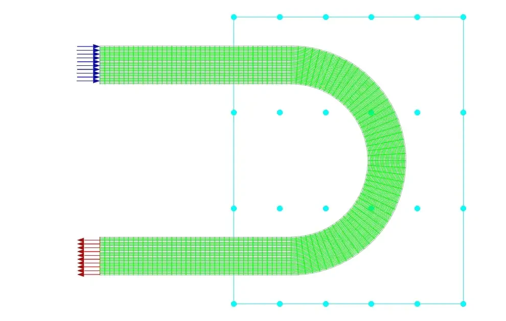
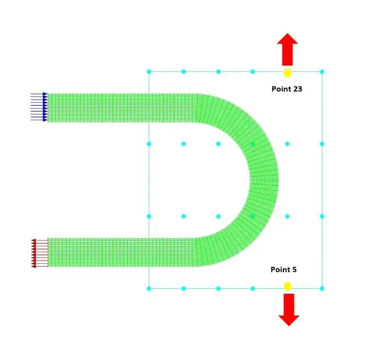
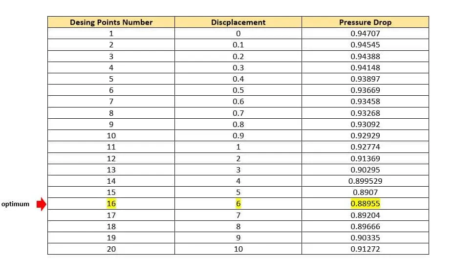
The constraints for other boundaries (Inlet and outlet) are set to fix. To begin the optimization process, you can define the motion for each of these points according to your engineering vision and physical understanding of the objective function. In this project, for point number 5, the displacement to the -y is considered and for point 23, the displacement to the +y is considered. Optimization has been done in 19 stages and for displacements of 0.1,0.2,0.3,0.4,0.5,0.6,0.7,0.8,0.9,1,2,3,4,5,6,7,8,9, and 10 meters for both points.
Geometry & Mesh
We designed this elbow in Design Modeler software. The length of the arms is 10 meters, the inner radius is 4 meters and the outer radius is 6 meters.
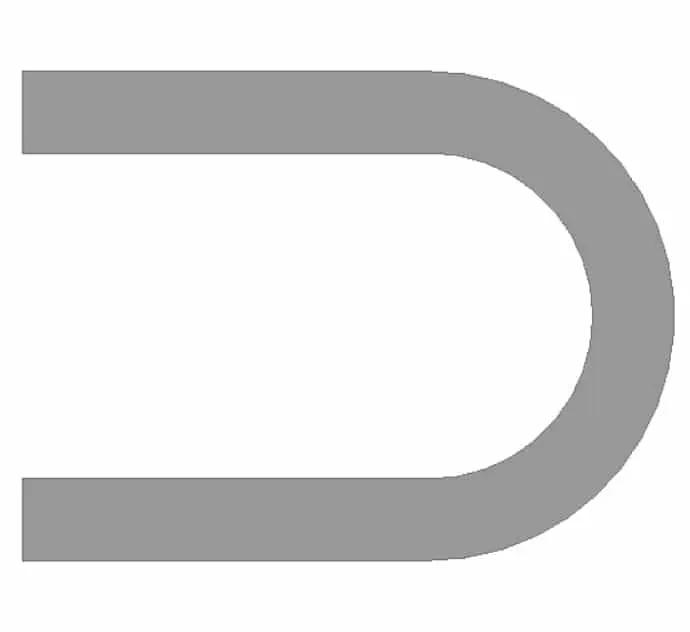
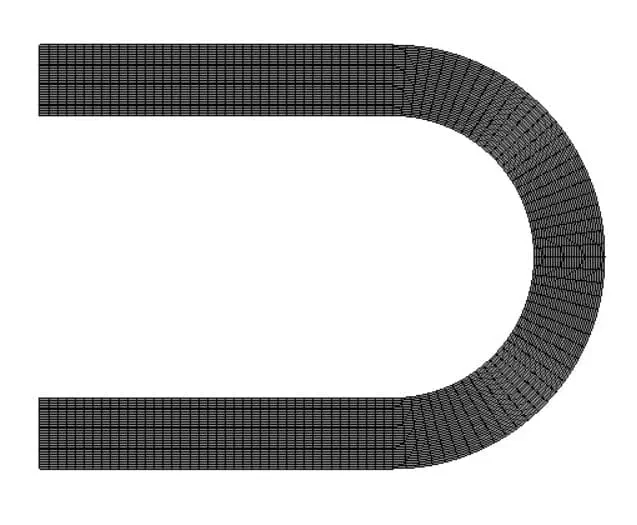
The meshing of this project has been done by Ansys Meshing software. The mesh type is fully structured and the element number is 3900.
Elbow CFD Simulation
We consider three assumptions for this simulation:
- we used the pressure-based solver due to the incompressibility.
- The gravity effect is ignored
- We performed this simulation in a steady state.
The following table represents a summary of the solution:
| Models(Viscous) | ||||
| Viscous | standard k-epsilon | standard wall function | ||
| Materials | ||||
| Fluid | Definition method | Fluent database | ||
| Material name | Water-liquid | |||
| Density | Constant =998.2 kg/m3 | |||
| Cell zone condition | ||||
| Material name | Water liquid | |||
| Boundary condition | ||||
| Inlet_flow | Type | Velocity inlet | ||
| Velocity magnitude normal to Boundary | 0.1 m/s | |||
| Outlet | Type | Pressure-outlet | ||
| Gauge pressure | 0 | |||
| Wall-elbow | Type | Stationary wall | ||
| Shear condition | No-slip condition | |||
| Solver configuration | ||||
| Pressure-velocity coupling | Scheme | SimpleC | ||
| Spatial Discretization | Gradient | Least squares cell-based | ||
| Pressure | Second-order | |||
| Momentum | Quick | |||
| Turbulent Kinetic Energy | First Order Upwind | |||
| Turbulent Dissipation Rate | First Order Upwind | |||
| Initialization | Initialization methods | Hybrid Initialization | ||
| Run calculation | Number of iterations | 1000 | ||
RBF Morph Results
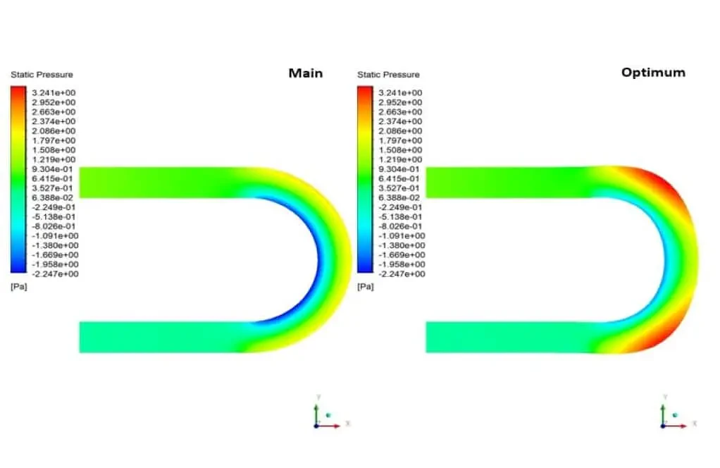
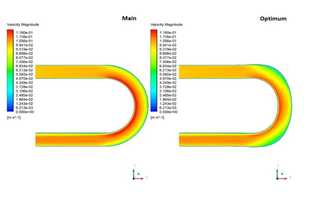
The results show the optimization for all modes. In fact, in all displacement modes, the pressure drop decreases as the curved area becomes more elongated. The optimum condition occurred when the displacement rate for both points was 6 meters.
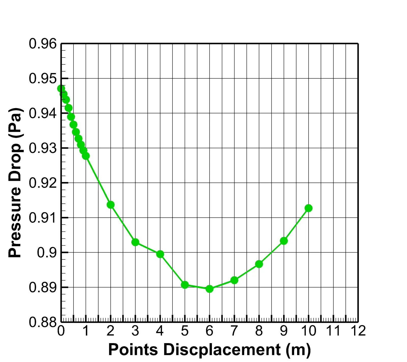
Pressure drop occurs when there is a pressure difference between two points in the fluid carrier network. When a liquid material enters one end of a piping system and leaves the other, pressure drop or pressure loss will occur. High flow velocities and/or high fluid viscosities result in a larger pressure drop across a section of pipe or a valve or elbow. Low velocity will result in lower or no pressure drop.
In this simulation, the pressure contour shows that with the elongation of the elbow bend, the outer regions of the geometry have more pressure. Also, under the influence of this elongation, the inner areas of the curve have increased pressure. On the other hand, the velocity contour indicates that the velocity in the bending regions has generally decreased. Therefore, it can be concluded that after optimizing the geometry, as was clear from the value of the optimization diagram, the pressure drop has reduced.