

FCC Riser Gas-Solid Separation System Simulation
Price: $48
The present problem simulates gas-solid flow within a fluid catalytic cracking (FCC) system using ANSYS Fluent software.
FCC Riser Gas-Solid Separation System Simulation
Price: $48
The present problem simulates gas-solid flow within a fluid catalytic cracking (FCC) system using ANSYS Fluent software.
FCC Riser Gas-Solid Separation System, CFD Simulation, ANSYS Fluent Training
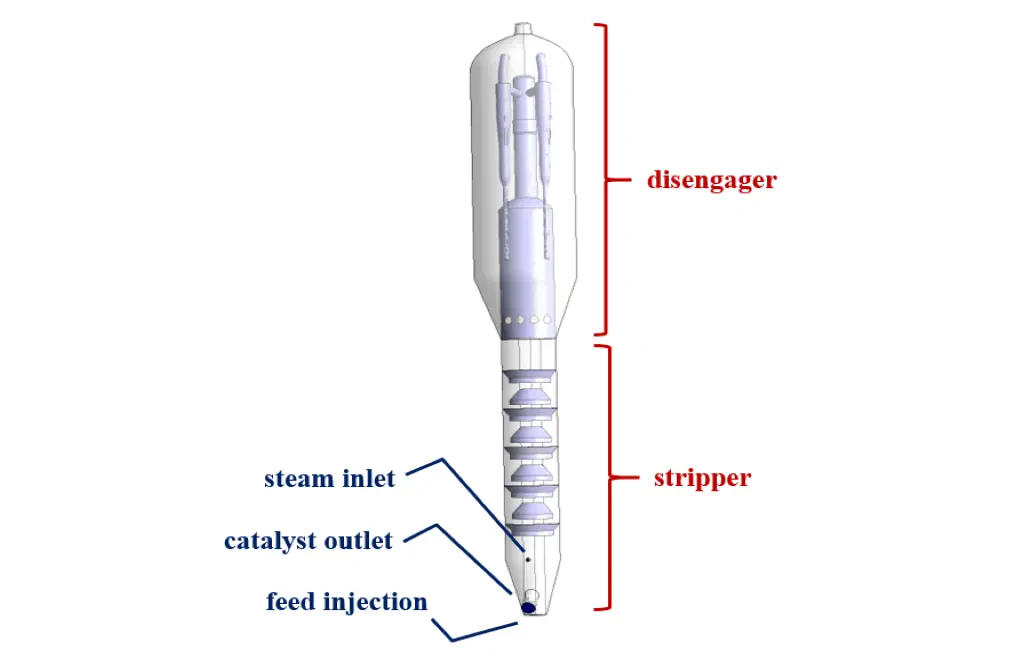
The present problem simulates gas-solid flow within a fluid catalytic cracking (FCC) system using ANSYS Fluent software. These FCC systems have many applications in chemical process units that are used to convert high-boiling oil ratios to lighter high-value products optimally. Inside FCC reactors, two important separate areas are defined, including a dilute area called the disengager and a dense area called the stripper. The disengager section is located in the upper part of the cylindrical chamber of the FCC reactor, which is responsible for separating the oil vapor from the catalyst particles. Therefore, in simulating this model, Eulerian multiphase flow is used.
This multiphase model can solve the momentum and conservation equations for each of the phases separately. Two materials are defined for this multiphase flow; So that oil vapor as a primary phase has a density equal to 3.471 kg.m-3 and a specific heat capacity equal to 1006.43 j.kg-1.K-1 and a thermal conductivity equal to 0.0242 Wm-.K-1, and a certain catalytic material as a secondary phase has a density equal to 1500 kg.m-3 and a specific heat capacity and thermal conductivity based on kinetic theory.
The oil vapor flow enters the reactor chamber from a special steam inlet with a velocity of 5.5 ms-1 and a temperature of 300 K, and a catalytic flow with oil vapor enters the feed injection inlet with a velocity of 18.57 ms-1 and a temperature of 300 K enter the chamber. The simulation process is performed with an unsteady solver for 20 seconds with a time step of 1 second.
FCC Geometry & Mesh
The present model is designed in three dimensions using Design Modeler software. The present model is a cylindrical reactor in which only a quarter of its geometric, symmetrical structure is designed to reduce computational costs. The upper part of the model is related to the disengager, and the lower part is related to the stripper.
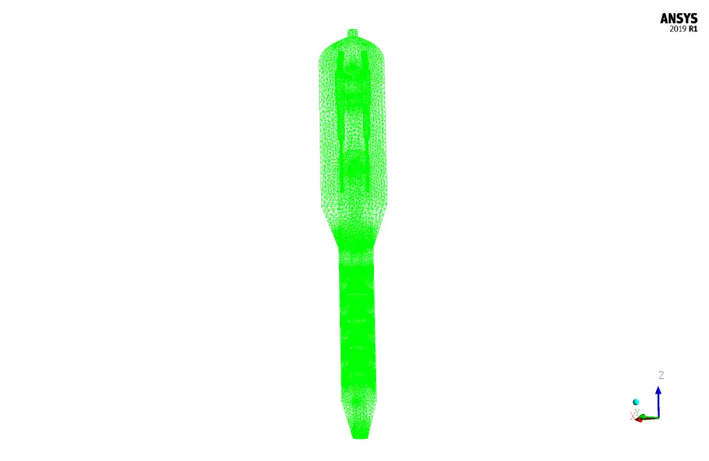
The meshing of the model has been done using ANSYS Meshing software, and the mesh type is unstructured. The element number is 2488759. The following figure shows the mesh.
FCC CFD Simulation
We consider several assumptions to simulate the present model:
- We perform a pressure-based solver.
- The simulation is unsteady.
- The gravity effect on the fluid is equal to -9.81 m.s-2 along the Z-axis.
The following table represents a summary of the defining steps of the problem and its solution:
| Models | |||
| Viscous | k-epsilon | ||
| k-epsilon model | standard | ||
| near wall treatment | standard wall functions | ||
| Multiphase model | Eulerian | ||
| formulation | implicit | ||
| number of Eulerian phases | 2 (oil vapor & catalyst) | ||
| Energy | On | ||
| Boundary conditions | |||
| Steam Inlet | Velocity Inlet | ||
| oil vapor | velocity magnitude | 5.5 m.s-1 | |
| temperature | 300 K | ||
| catalyst | velocity magnitude | 0 m.s-1 | |
| temperature | 300 K | ||
| Feed Injection | Velocity Inlet | ||
| oil vapor | velocity magnitude | 18.57 m.s-1 | |
| temperature | 300 K | ||
| catalyst | velocity magnitude | 18.57 m.s-1 | |
| temperature | 300 K | ||
| Product Outlet | Pressure Outlet | ||
| gauge pressure | 0 pascal | ||
| Inner Walls | Wall | ||
| wall motion | stationary wall | ||
| thermal condition | coupled | ||
| Baffles, disengager, stripper | Wall | ||
| wall motion | stationary wall | ||
| heat flux | 0 W.m-2 | ||
| Methods | |||
| Pressure-Velocity Coupling | Phase Coupled SIMPLE | ||
| Pressure | PRESTO | ||
| momentum | second-order upwind | ||
| turbulent kinetic energy | second-order upwind | ||
| turbulent dissipation rate | second-order upwind | ||
| volume fraction | quick | ||
| energy | second-order upwind | ||
| Initialization | |||
| Initialization methods | Standard | ||
| gauge pressure | 0 pascal | ||
| z-velocity for oil vapor | 18.57 m.s-1 | ||
| z-velocity for catalyst | 18.57 m.s-1 | ||
| temperature for oil vapor | 300 K | ||
| temperature for catalyst | 300 K | ||
| volume fraction for catalyst | 0.6 | ||
Results
At the end of the solution process, three-dimensional contours related to the pressure, velocity, and volume fraction of each of the phases in the model are obtained. The results are related to the last second of the simulation process (20 seconds).