

Finned Shell and Tube Heat Exchanger CFD simulation, ANSYS Fluent Training
Price: $8
The present problem simulates water flow and heat transfer inside a wavy-shaped finned shell and tube heat exchanger using ANSYS Fluent software.
Finned Shell and Tube Heat Exchanger CFD simulation, ANSYS Fluent Training
Price: $8
The present problem simulates water flow and heat transfer inside a wavy-shaped finned shell and tube heat exchanger using ANSYS Fluent software.
shell and tube heat exchanger Project Description
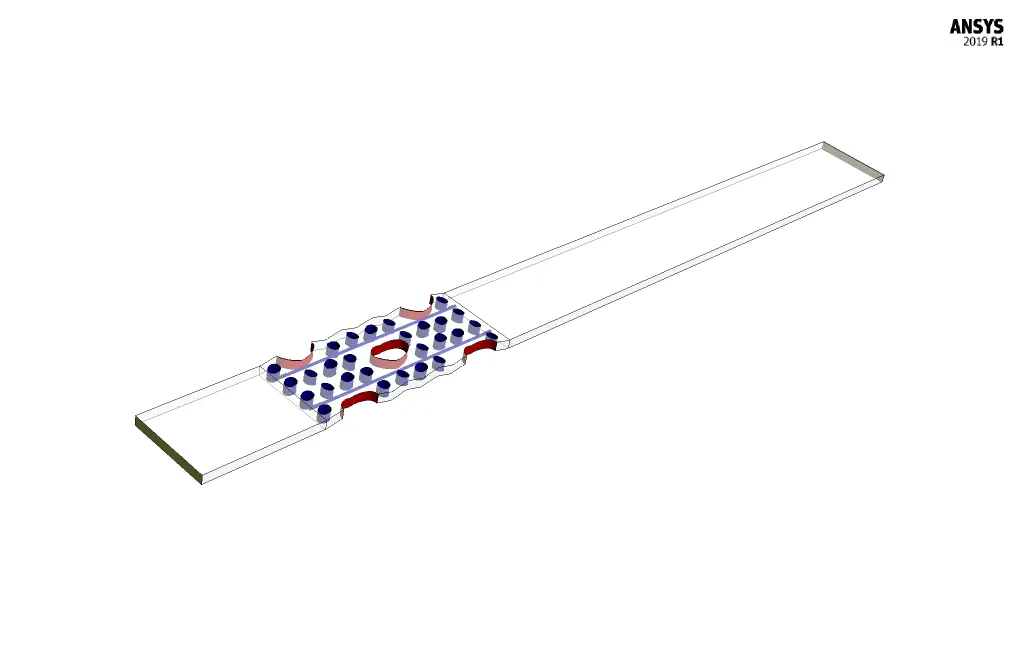
The present problem simulates water flow and heat transfer inside a finned shell and tube heat exchanger using ANSYS Fluent software. The simulation model deals with a sample part of a heat exchanger. This section includes three computational areas for water flow; So that there is an area for upstream flow and one area for downstream flow and a middle area includes several tubes and fins. The water flow enters the computational zone with a velocity of 0.5 m.s-1 and a temperature of 343 K.
The fins merely act as a barrier or a kind of porous medium and have a thermal insulation boundary condition; While the tubes are assumed to have a constant temperature equivalent to 293 K on their walls.
Geometry & Mesh
The present model is designed in three dimensions using Design Modeler software. The geometry of the model is related to a part of the heat exchanger, the middle part of which has a sinusoidal or wavy structure and has several tubes and fins.
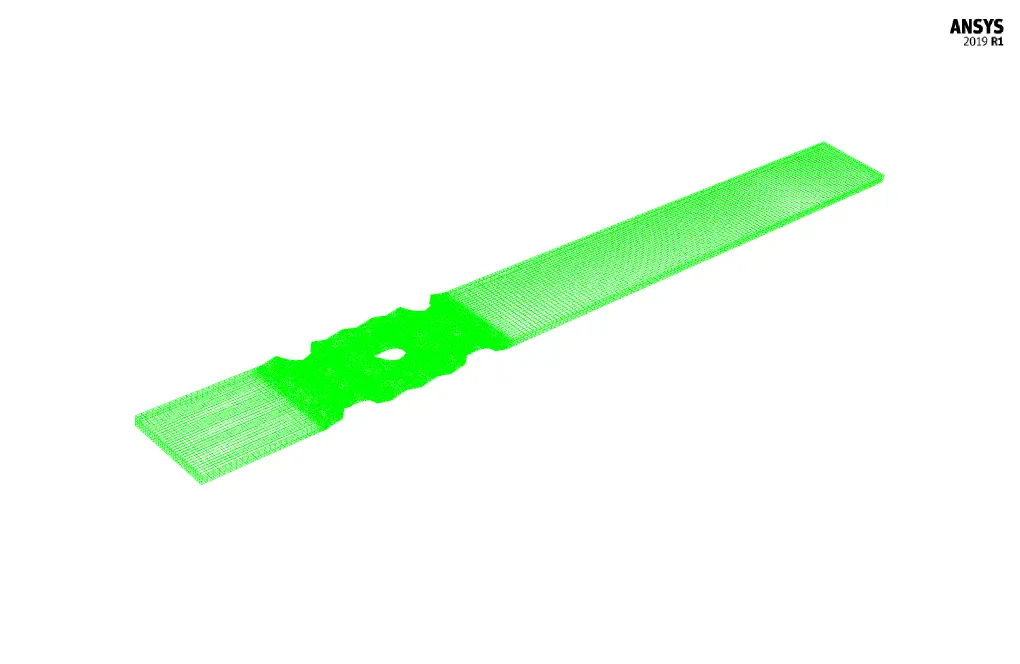
The meshing of the model has been done using ANSYS Meshing software and the mesh type is unstructured. The element number is 803864. The following figure shows the mesh.
shell and tube heat exchanger CFD Simulation
To simulate the present model, several assumptions are considered:
- We perform a pressure-based solver.
- The simulation is steady.
- The gravity effect on the fluid is ignored.
A summary of the defining steps of the problem and its solution is given in the following table:
| Models | ||
| Viscous | k-epsilon | |
| k-epsilon model | standard | |
| near-wall treatment | standard wall function | |
| Energy | On | |
| Boundary conditions | ||
| Inlet | Velocity Inlet | |
| velocity magnitude | 0.5 m.s-1 | |
| temperature | 343 K | |
| Outlet | Pressure Outlet | |
| gauge pressure | 0 pascal | |
| Wall - Tube | ||
| wall motion | stationary wall | |
| temperature | 293 K | |
| Wall - Fin | ||
| wall motion | stationary wall | |
| heat flux | 0 W.m-2 | |
| Methods | ||
| Pressure-velocity coupling | SIMPLE | |
| pressure | second order | |
| momentum | second order upwind | |
| turbulent kinetic energy | first order upwind | |
| turbulent dissipation rate | first order upwind | |
| energy | second order upwind | |
| Initialization | ||
| Initialization methods | standard | |
| gauge pressure | 0 pascal | |
| x-velocity | 0.5 m.s-1 | |
| y-velocity & z-velocity | 0 m.s-1 | |
| temperature | 343 K | |
Results
At the end of the solution process, two-dimensional and three-dimensional contours related to pressure, velocity and temperature, as well as velocity vectors and path lines are obtained.