Floating Vessel Motion in Water by Dynamic Mesh, ANSYS Fluent Training
Price: $60
- The problem numerically simulates the Floating Vessel Motion in Water using ANSYS Fluent software.
- We design the 3-D model with the Design Modeler software.
- We mesh the model with ANSYS Meshing software, and the element number equals 902808.
- We perform this simulation as unsteady (Transient).
- We use the Dynamic Mesh model to define the instantaneous change of meshing.
- We use a UDF to define the motion with two degrees of freedom.
- We use the VOF Multiphase model and the Open Channel condition to define the water level inside the air.

Description
The present problem simulates the motion of a floating vessel in the water by dynamic mesh method using ANSYS Fluent software. In this simulation, a computational domain of water with a certain height level is designed with a floating vessel on the water's surface.
The present model is designed in three dimensions using Design Modeler software. The mentioned floating vessel is designed in the middle of three cubic computing domains.
For ease of simulation, the floating vessel should be designed so that its center of gravity is at the center of the vertical direction (z-axis).
The meshing of the model has been done using ANSYS Meshing software. The mesh type is unstructured near the floating vessel and structured in the other parts. The element number is 902808.
Floating Vessel Methodology
In such models, we need a momentary and time-dependent change in meshing based on the type of displacement at adjacent boundaries of grids.
Therefore, the Dynamic Mesh model defines the instantaneous change of meshing. Initially, a floating vessel was designed for this simulation, and three computational zones were generated around it. Smoothing and Remeshing methods have been used to determine dynamic mesh methods.
According to the smoothing method, the number of nodes or cell connections does not change and only adjusts the mesh of an area by moving or deforming the boundaries.
However, the remeshing method is used when the boundary displacement is large compared to the size of the local cells to reconstruct the destructive cells of the critical size limit.
Six degrees of freedom (6-DOF) have also been used to define the type of dynamic mesh behavior. The model can move and relocate in six transitional and rotational directions.
To define areas with a dynamic mesh, a small rectangular cube area (around the floating vessel) is created as a Moving area, and a slightly larger area around the moving section is defined as a Deforming area.
Finally, a large general area around these areas is designed to be a Stationary area. The floating vessel part and the moving area are defined as Rigid Bodies.
This means that the floating vessel and a limited moving area act as a rigid and integrated body and can be moved in a transitional or rotational manner without any change in meshing. Since the vessel has only two degrees of freedom and can only move up and down in the vertical direction (z-axis) or rotate around its central axis (y-axis), and has a constraint in other directions (It does not have any transitional or rotational motion), a UDF is used to define this type of motion with two degrees of freedom.
It should be noted that in the section's settings related to the rigid body, the spatial coordinates of the center of gravity of the floating vessel and the axis of its rotation around itself must be defined. The vessel is defined as a floating object on the water's surface.
The VOF multiphase flow model should be used; So that air is defined in the upper part of the computational domain and water in the lower part. Air and water phases flow at speeds equal to 1.44 m/s in the horizontal direction (x-axis) and exit at a pressure equivalent to atmospheric pressure.
At the outlet boundary of the model, the Open Channel condition is used to define the water level. Due to the main nature of the model based on the use of dynamic mesh, the simulation process should be defined in terms of time (Transient solver).
The present model performs the simulation process in 7 seconds with a time step of 0.01 seconds.
Floating Vessel Conclusion
At the end of the solution process, two-dimensional contours related to the pressure on the floating vessel and two-dimensional contours related to the velocity and volume fraction of each air and water phase are obtained in the areas around the floating vessel.
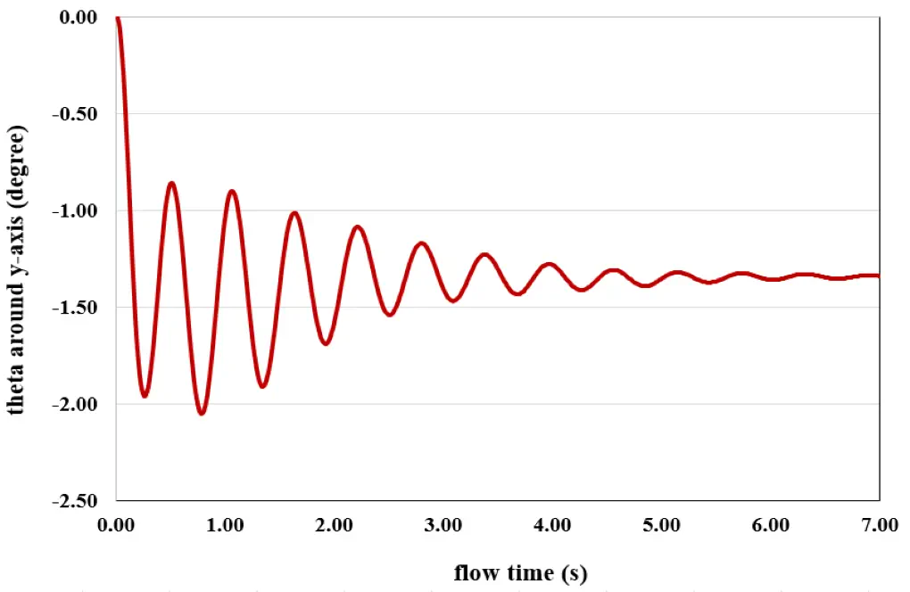
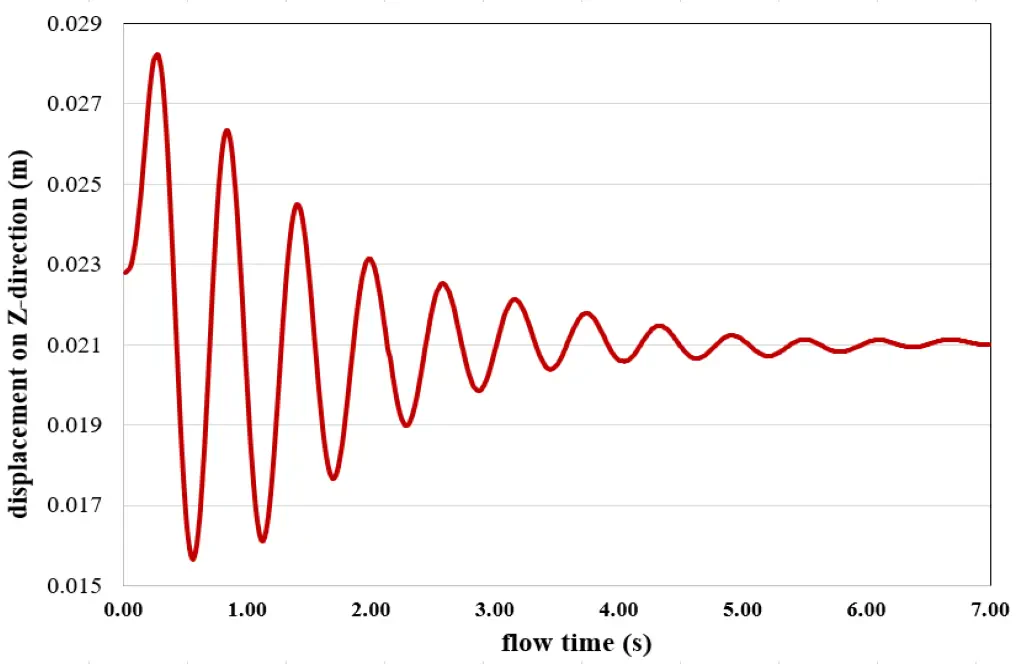
These contours correspond to the last second of the simulation process. Also, the graph of the amount of displacement of the vessel in the vertical direction (z-axis) in terms of time passage and the amount of rotation angle of the floating vessel around its central axis (y-axis) in terms of time are obtained.
These graphs show the angular and transitional spatial changes over 7 seconds. As the amplitude of the oscillation of the changes in the two graphs is clear, the changes reach their minimum in the seventh second, and we can say that the rotational and the transition motion are damped after this time.
Also, the figure shows that the floating vessel position in the seventh second at the position z = 0.021 and the angle Y_theta = -1.338 reaches stability.