

Fluid Separation of Turbulent Flow Over a Step, Paper Numerical Validation by ANSYS Fluent
Price: $12
The present problem simulates the separation of fluid flow passing through a step and the effect of suction and blower control jets on controlling the separation of fluid using ANSYS Fluent software. This simulation is based on the information of a reference article "A force reduced-order approach for optimal control of turbulent flow over backward-facing step using POD analysis and perturbation method", and its results are compared and validated with the results in the article.
Paper Description
The present problem simulates the separation of fluid flow passing through a step and the effect of suction and blower control jets on controlling the separation of fluid using ANSYS Fluent software. This simulation is based on the information of a reference article "A force reduced-order approach for optimal control of turbulent flow over backward-facing step using POD analysis and perturbation method", and its results are compared and validated with the results in the article. In this simulation, the fluid flow enters the channel horizontally at a speed equivalent to 1 ms-1 and then passes through a step to a height of 1 m within 30 m inside the channel, leading to separation.
Suction and blow control jets are used at the upper and lower edges of the stairs to control fluid separation. So that the fluid flow is blown into the channel from the bottom of the stairs and is sucked out from the top edge of the stairs. Therefore, the input speed equal to +1 m.s-1 has been used for the special blowing limit, and the input speed equal to -1 m.s-1 has been used for the suction limit.
Geometry & Mesh
The present model is designed in two dimensions using Design Modeler software. This model belongs to a part of a canal that has a step 1 m high. At the top edge of the stairs, the border is defined as a 0.1 m long sucker and at the bottom edge of the stairs, the boundary is defined as a 0.1 m long blower. We carry out the model's meshing using ANSYS Meshing software. The mesh type is structured. The element number is 15000. The following figure shows the Mesh.
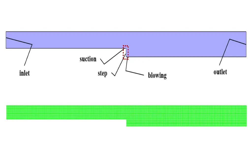
Fluid Separation CFD Simulation
We consider several assumptions to simulate the present model:
- We perform a pressure-based solver.
- The simulation is steady.
- The gravity effect on the fluid is ignored.
The following table represents a summary of the defining steps of the problem and its solution:
| Models (Fluid Separation) | ||
| Viscous | k-epsilon | |
| k-epsilon model | RNG | |
| near wall treatment | standard wall function | |
| Boundary conditions (Fluid Separation) | ||
| Input | Velocity Inlet | |
| velocity magnitude | 1 m.s-1 | |
| Output | Outflow | |
| flow rate weighting | 1 | |
| Blow | Velocity Inlet | |
| velocity magnitude | 0.1 m.s-1 | |
| Suction | Velocity Inlet | |
| velocity magnitude | -0.1 m.s-1 | |
| wall motion | stationary wall | |
| Methods (Fluid Separation) | ||
| Pressure-Velocity Coupling | SIMPLE | |
| pressure | standard | |
| momentum | quick | |
| turbulent kinetic energy | quick | |
| turbulent dissipation rate | quick | |
| Initialization (Fluid Separation) | ||
| Initialization methods | Hybrid | |
Paper Validation
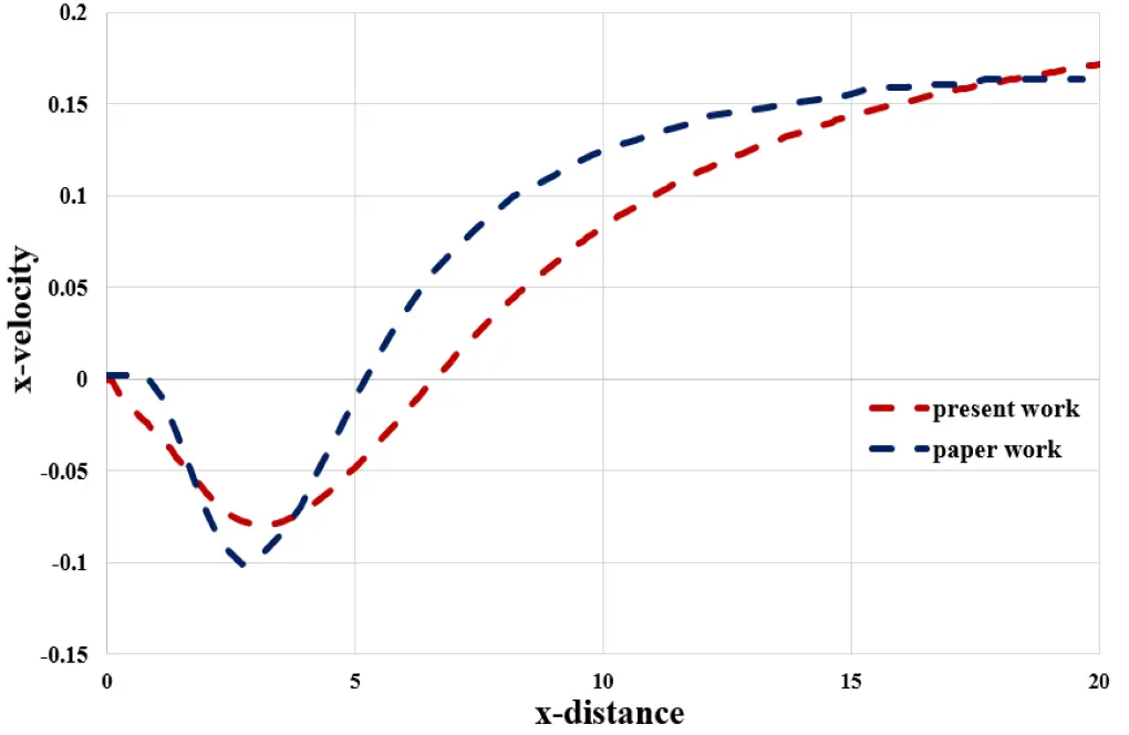
The present simulation's validation is based on the diagram in Figure 5 of the mentioned article. This diagram relates to changes in the value of horizontal velocity in terms of location in the horizontal direction. The study location is at the height of 0.04 m from the canal floor and in the area after the stairs and at a distance of 20 m after the stairs.
Results & Discussion
At the end of the solution process, two-dimensional contours related to turbulence, velocity, pressure, and kinetic energy are obtained.