
Thermal Fluid-Structure Interaction (Thermal FSI) in ANSYS
Price:
$400
$279
Master the FSI process with our “Thermal Fluid-Structure Interaction (Thermal FSI): All Levels” CFD course using ANSYS Fluent. From basics to advanced, learn to perform procedures of Thermal FSI simulation by two overall methodologies: 1) Intrinsic FSI in ANSYS Fluent solver (by Structure model); 2) External FSI in ANSYS Workbench environment (by coupling different Structural and Thermal solvers). This course equips you with the essential skills to model the simultaneous interaction of fluid and solid under thermal effects in all engineering fields using CFD. Ideal for beginners and experts alike, this course enhances your capabilities in Thermal FSI analysis for cutting-edge research and industrial applications.
Gas Turbine, Thermal FSI, ANSYS Fluent CFD Simulation
DescriptionIn this project, we present a simulation of a Gas Turbine Blade under Thermal FSI via ANSYS Fluent software. We have modeled a single blade from one of the stages of a gas turbine, which contains an internal channel with fine holes for the cooling process. The computational domain consists of a fluid zone dedicated to the streams and a solid region as the pipe body surrounding the fluid zone.What is FSI?Air flows throughout the turbine blade construction and through its holes. So, the fluid flow can expose a pressure load on the inner wall of the T-junction pipe. In such a condition, analysis of Fluid-Structure Interaction (FSI) becomes important. It means that both fluid and structural calculations are available.Why Thermal FSI?The cooling airflow inside the turbine's internal channel is in contact with the hot body of the turbine blade. So, it is expected that a thermal load will be imposed on the solid body. As a result, the focus is on the Thermal FSI. It means the solution data of fluid flow, structural, and thermal calculations are coupled.1-way or 2-way?Only the effect of the pressure and thermal loads of the flow on the inner wall of the turbine blade is analyzed; no need to consider the effect of the solid blade structure on the nearby flow. Hence, it is called One-way FSI.MethodologyFor FSI simulations, we recommend two general methods: intrinsic FSI and extrinsic FSI. If the calculation of both the fluid and the structure is performed only in ANSYS Fluent, it is called Intrinsic FSI. Meanwhile, if the calculation process of the fluid and the structure is performed in different and individual solvers and then coupled with each other, it is referred to as Extrinsic FSI.Intrinsic FSI:In this project, we have used the intrinsic FSI method. We performed fluid and solid analyses for both the fluid and structural domains, using only the ANSYS Fluent solver. It means that no external solver is required for the interaction between the fluid and the structure.Structure Model:For the internal FSI, we have used the Structure model. By this option, the calculations for solids are also added to fluids.Linear or Non-linear Elasticity?We used the Linear Elasticity method for structural analysis. It means that the deformation or displacement of the structure is proportional to the force value exerted by the fluid.Thermal Effect:Since we intend to analyze the thermal load in addition to the overall pressure load, we enable the Thermal Effect option.ConclusionWe have investigated the results by analyzing the interaction between fluid and solid.Structural:We obtained the contours related to the distribution of the total displacement and von Mises stress on the inner wall of the turbine blade (interface between fluid and solid zones), which is exposed to the cooling flow.The results confirm that the maximum deformation and stress are concentrated in the upper zones of the blade, because the fixed support is defined on the central turbine body. In addition, since the upper regions of the gas turbine blade are exposed to the minimum values of the internal cooling process, the highest thermal stress may appear.
Thermal Fluid-Structure Interaction (Thermal FSI) in ANSYS
Price:
$400
$279
Master the FSI process with our “Thermal Fluid-Structure Interaction (Thermal FSI): All Levels” CFD course using ANSYS Fluent. From basics to advanced, learn to perform procedures of Thermal FSI simulation by two overall methodologies: 1) Intrinsic FSI in ANSYS Fluent solver (by Structure model); 2) External FSI in ANSYS Workbench environment (by coupling different Structural and Thermal solvers). This course equips you with the essential skills to model the simultaneous interaction of fluid and solid under thermal effects in all engineering fields using CFD. Ideal for beginners and experts alike, this course enhances your capabilities in Thermal FSI analysis for cutting-edge research and industrial applications.
-
Section 1
Thermal FSI Concepts
-
This chapter reviews the general concepts of fluid-structure interaction (FSI), with a focus on thermal FSI. So, it is known as Thermal FSI.It discusses two overall methodologies for simulating thermal FSI cases: Intrinsic FSI and Extrinsic FSI.In the first approach, all calculations of the fluid and solid domains and the interaction between them are performed by the Fluent solver. For this purpose, the Structure model with enabling Thermal effects is used.In the second approach, the calculations of the fluid and solid domains are performed separately and individually by different solvers. Then, by defining data transfer, the solvers are coupled together. For this purpose, the Fluent solver is used to solve the fluid flow, and the Structural and Thermal solvers are used to solve the solid domain.
Lesson 1 7m 6s
-
-
Section 2
Manifold: Thermal FSI, 2-way, ANSYS Workbench (External FSI)
-
DescriptionIn this project, we present a simulation of an Exhaust Manifold under Thermal FSI via ANSYS software. We have modeled a simple exhaust manifold consisting of a fluid domain dedicated to the gas flow and a solid region as the manifold body surrounding the fluid zone.What is FSI?The gas flow is discharged through the exhaust manifold. So, the gas flow can expose a pressure load on the inner wall of the manifold. In such a condition, analysis of Fluid-Structure Interaction (FSI) becomes important. It means that both fluid and structural calculations are available.Why Thermal FSI?Hot gas flows throughout the exhaust manifold. So, it is expected that a thermal load will be imposed on the solid body. As a result, the focus is on the Thermal FSI. It means the solution data of fluid flow, structural, and thermal calculations are coupled.1-way or 2-way?First, the effect of the pressure and thermal loads of the gas flow on the inner wall of the exhaust manifold is analyzed. Next, the effect of the solid manifold structure, deformed or displaced, on the nearby gas flow is investigated. Hence, it is called Two-way FSI.MethodologyFor FSI simulations, we recommend two general methods: intrinsic FSI and extrinsic FSI. If the calculation of both the fluid and the structure is performed only in ANSYS Fluent, it is called Intrinsic FSI. Meanwhile, if the calculation process of the fluid and the structure is performed in different and individual solvers and then coupled with each other, it is referred to as Extrinsic FSI.Extrinsic FSI:In this project, we have used the external FSI method. We performed the structural analysis corresponding to the manifold solid body in the ANSYS Steady-State Thermal solver, while we performed the fluid analysis corresponding to the gas flow in the ANSYS Fluent (Fluid Flow) solver.System Coupling:The steady-state Thermal solver and the Fluent solver are defined separately in the ANSYS Workbench environment. Then, fluid and solid calculations are performed to obtain the solution data. In this case study, we consider the inner wall of the exhaust manifold as the fluid-structure interface to couple the calculations. Therefore, the data transfer between the fluid and structure solvers is defined by the System Coupling tool.How to define Data Transfer?In the coupling system, we define two Data Transfers. One is the data transfer in the form of Heat Flow from fluid to structural solver, and the other is the data transfer in the form of Temperature, from structural to fluid solver.ConclusionWe have investigated the results with two approaches: thermal fluid analysis (from Fluent) and thermal structural analysis (from steady-state Thermal).Thermal Fluid:We obtained the distribution of the temperature and heat flux of the airflow within the manifold exhaust, as well as the temperature and heat flux on the surface of the manifold’s internal wall. The results show that heat transfer occurs between the fluid flow and the structural body, such that the heat flux is lost from the hot stream adjacent to the inner wall of the manifold.Thermal Structural:We obtained the contours related to the temperature and heat flux distributions on the manifold structure body. The results show that heat transfer occurs between the fluid flow and the structural body, such that the heat flux is absorbed by the internal surface of the manifold body.
Lesson 1 14m 25s
-
-
Section 3
T-Junction: Thermal FSI, 1-way, ANSYS Workbench (External FSI)
-
DescriptionIn this project, we present a simulation of a T-junction Pipe under Thermal FSI via ANSYS software. We have modeled a simple T-junction containing a main pipe and a branch, so that two streams with different temperatures would be mixed. The computational domain consists of a fluid zone dedicated to the streams and a solid region as the pipe body surrounding the fluid zone.What is FSI?Two fluid streams flow through the T-junction pipe. So, the fluid flow can expose a pressure load on the inner wall of the T-junction pipe. In such a condition, analysis of Fluid-Structure Interaction (FSI) becomes important. It means that both fluid and structural calculations are available.Why Thermal FSI?Two streams with different temperatures flow throughout the T-junction. So, it is expected that a thermal load will be imposed on the solid body. As a result, the focus is on the Thermal FSI. It means the solution data of fluid flow, structural, and thermal calculations are coupled.1-way or 2-way?Only the effect of the pressure and thermal loads of the flow on the inner wall of the T-junction pipe is analyzed; no need to consider the effect of the solid T-junction structure on the nearby flow. Hence, it is called One-way FSI.MethodologyFor FSI simulations, we recommend two general methods: intrinsic FSI and extrinsic FSI. If the calculation of both the fluid and the structure is performed only in ANSYS Fluent, it is called Intrinsic FSI. Meanwhile, if the calculation process of the fluid and the structure is performed in different and individual solvers and then coupled with each other, it is referred to as Extrinsic FSI.Extrinsic FSI:In this project, we have used the external FSI method. We performed the structural and thermal analysis corresponding to the T-junction solid body in the ANSYS Static Structural and ANSYS Steady-State Thermal solvers, respectively, while we performed the fluid analysis corresponding to the streams in the ANSYS Fluent (Fluid Flow) solver.How to use solvers?The static Structural solver, the steady-state Thermal solver, and the Fluent solver are defined separately in the ANSYS Workbench environment. Then, fluid and solid calculations are performed to obtain the solution data. In this case study, we consider the inner wall of the T-junction pipe as the fluid-structure interface to couple the calculations.How to couple solvers?Note that the data between the fluid and structural solvers is transferred directly. First, by Fluent calculation, the thermal data from the fluid flow is transmitted as input in the form of Temperature Load to the Thermal solver. Then, on one hand, by steady-state Thermal calculations, the thermal data in the form of Temperature Body Load from the thermal solver, and on the other hand, by Fluent calculations, the flow data in the form of Pressure Body Load are transmitted to the static Structural solver.ConclusionWe have investigated the results with three approaches: fluid analysis (from Fluent), thermal analysis (from steady-state Thermal), and structural analysis (from static Structural).Fluid:We obtained the distribution of the temperature and pressure of the water flowing within the T-junction, as well as the surface temperature and pressure on the internal wall of the T-junction.Thermal:We obtained the contours related to the temperature distributions on the T-junction structure body. The results show that heat transfer occurs between the fluid and the structure.Structural:We obtained the contours related to the total deformation and von Mises stress on the T-junction structure body. The results confirm that the T-junction body undergoes considerable deformation under pressure and thermal stresses.
Lesson 1 17m 29s
-
-
Section 4
Bent Pipe: Thermal FSI, Comparison analysis, ANSYS Fluent (Intrinsic FSI)
-
DescriptionIn this project, we present a simulation of a Bent Pipe under Thermal FSI via ANSYS Fluent software. We have modeled a simple pipe containing two bends. The computational domain consists of a fluid zone dedicated to the water flow and a solid region as the pipe body surrounding the fluid zone.What is FSI?The water flows throughout the pipe with two elbows. So, the fluid flow can expose a pressure load on the inner wall of the pipe (especially in bend zones). In such a condition, analysis of Fluid-Structure Interaction (FSI) becomes important. It means that both fluid and structural calculations are available.Why Thermal FSI?The hot water flows throughout the bent pipe. So, it is expected that a thermal load will be imposed on the solid body. As a result, the focus is on the Thermal FSI. It means the solution data of fluid flow, structural, and thermal calculations are coupled.1-way or 2-way?First, the effect of the pressure and thermal loads of the flow on the inner wall of the pipe is analyzed. Next, the effect of the solid pipe structure, deformed or displaced, on the nearby flow is investigated. Hence, it is called Two-way FSI.MethodologyFor FSI simulations, we recommend two general methods: intrinsic FSI and extrinsic FSI. If the calculation of both the fluid and the structure is performed only in ANSYS Fluent, it is called Intrinsic FSI. Meanwhile, if the calculation process of the fluid and the structure is performed in different and individual solvers and then coupled with each other, it is referred to as Extrinsic FSI.Intrinsic FSI:In this project, we have used the intrinsic FSI method. We performed fluid and solid analyses for both the fluid and structural domains, using only the ANSYS Fluent solver. It means that no external solver is required for the interaction between the fluid and the structure.Structure Model:For the internal FSI, we have used the Structure model. By this option, the calculations for solids are also added to fluids.Linear or Non-linear Elasticity?We used the Linear Elasticity method for structural analysis. It means that the deformation or displacement of the structure is proportional to the force value exerted by the fluid.Comparison analysis:To investigate the importance of thermal FSI, we carried out this project in two steps:In the first simulation, we ignored the energy equation and heat transfer and focused only on the hydraulic force of the flow.In the second simulation, we enabled the energy equation and heat transfer so that thermal loads were also included in the FSI analysis.Thermal Effect:Therefore, in the thermal FSI simulation, since we intend to analyze the thermal load in addition to the overall pressure load, we need to enable the Thermal Effect option.Why Dynamic Mesh?Since we have been using two-way FSI, the deformed structure can affect the behavior of the fluid flowing near it. So we need to also consider the deformation of the fluid domain over time. Therefore, we used the Dynamic Mesh tool. By this, we can define the interface between the fluid and the structure for coupling purposes.ConclusionWe have investigated the results by analyzing the interaction between fluid and solid.Comparison:We aim to represent a comparative analysis between the FSI due to the fluid pressure load and the FSI affected by both the pressure and thermal load.So, we obtained the contour corresponding to the distribution of the total displacement and von Mises stress. These contours are both for the inner wall of the pipe, which is exposed to the fluid flow, and for the outer wall of the pipe, which is freely movable.The results show that the maximum displacement appears in the bends or elbows of the pipe. This confirms that these regions undergo the highest deformation due to the fluid flowing.In addition, the stress is considerable near bends and elbows. However, since the two ends of the pipe are considered as fixed supports, the highest stress is shown.
Lesson 1 14m 30s
-
-
Section 5
T-junction: Thermal FSI, 2-way, ANSYS Fluent (Intrinsic FSI)
-
DescriptionIn this project, we present a simulation of a T-junction Pipe under Thermal FSI via ANSYS Fluent software. We have modeled a simple T-junction containing a main pipe and a branch, so that two streams with different temperatures would be mixed. The computational domain consists of a fluid zone dedicated to the streams and a solid region as the pipe body surrounding the fluid zone.What is FSI?Two fluid streams flow through the T-junction pipe. So, the fluid flow can expose a pressure load on the inner wall of the T-junction pipe. In such a condition, analysis of Fluid-Structure Interaction (FSI) becomes important. It means that both fluid and structural calculations are available.Why Thermal FSI?Two streams with different temperatures flow throughout the T-junction. So, it is expected that a thermal load will be imposed on the solid body. As a result, the focus is on the Thermal FSI. It means the solution data of fluid flow, structural, and thermal calculations are coupled.1-way or 2-way?First, the effect of the pressure and thermal loads of the flow on the inner wall of the T-junction pipe is analyzed. Next, the effect of the solid T-junction structure, deformed or displaced, on the nearby flow is investigated. Hence, it is called Two-way FSI.MethodologyFor FSI simulations, we recommend two general methods: intrinsic FSI and extrinsic FSI. If the calculation of both the fluid and the structure is performed only in ANSYS Fluent, it is called Intrinsic FSI. Meanwhile, if the calculation process of the fluid and the structure is performed in different and individual solvers and then coupled with each other, it is referred to as Extrinsic FSI.Intrinsic FSI:In this project, we have used the intrinsic FSI method. We performed fluid and solid analyses for both the fluid and structural domains, using only the ANSYS Fluent solver. It means that no external solver is required for the interaction between the fluid and the structure.Structure Model:For the internal FSI, we have used the Structure model. By this option, the calculations for solids are also added to fluids.Linear or Non-linear Elasticity?We used the Linear Elasticity method for structural analysis. It means that the deformation or displacement of the structure is proportional to the force value exerted by the fluid.Thermal Effect:Since we intend to analyze the thermal load in addition to the overall pressure load, we enable the Thermal Effect option.Why Dynamic Mesh?Since we have been using two-way FSI, the deformed structure can affect the behavior of the fluid flowing near it. So we need to also consider the deformation of the fluid domain over time. Therefore, we used the Dynamic Mesh tool. By this, we can define the interface between the fluid and the structure for coupling purposes.ConclusionWe have investigated the results by analyzing the interaction between fluid and solid.Structural:We obtained the contours related to the distribution of the total displacement and von Mises stress on the T-junction structure body (both for the inner wall of the pipe, which is exposed to the fluid flow, and for the outer wall, which is freely movable.The results confirm that the maximum displacement appears in the T-junction zone, between the fixed support at the end of each branch. It means that T-junction regions undergo the highest deformation due to the fluid flowing.On the other hand, the stress reaches its highest value at the adjacent to each support. In addition, the branch containing the hotter fluid shows a higher stress, which could be due to the effect of thermal stress.
Lesson 1 15m 36s
-
-
Section 6
Gas Turbine: Thermal FSI, 1-way, ANSYS Fluent (Intrinsic FSI)
-
DescriptionIn this project, we present a simulation of a Gas Turbine Blade under Thermal FSI via ANSYS Fluent software. We have modeled a single blade from one of the stages of a gas turbine, which contains an internal channel with fine holes for the cooling process. The computational domain consists of a fluid zone dedicated to the streams and a solid region as the pipe body surrounding the fluid zone.What is FSI?Air flows throughout the turbine blade construction and through its holes. So, the fluid flow can expose a pressure load on the inner wall of the T-junction pipe. In such a condition, analysis of Fluid-Structure Interaction (FSI) becomes important. It means that both fluid and structural calculations are available.Why Thermal FSI?The cooling airflow inside the turbine's internal channel is in contact with the hot body of the turbine blade. So, it is expected that a thermal load will be imposed on the solid body. As a result, the focus is on the Thermal FSI. It means the solution data of fluid flow, structural, and thermal calculations are coupled.1-way or 2-way?Only the effect of the pressure and thermal loads of the flow on the inner wall of the turbine blade is analyzed; no need to consider the effect of the solid blade structure on the nearby flow. Hence, it is called One-way FSI.MethodologyFor FSI simulations, we recommend two general methods: intrinsic FSI and extrinsic FSI. If the calculation of both the fluid and the structure is performed only in ANSYS Fluent, it is called Intrinsic FSI. Meanwhile, if the calculation process of the fluid and the structure is performed in different and individual solvers and then coupled with each other, it is referred to as Extrinsic FSI.Intrinsic FSI:In this project, we have used the intrinsic FSI method. We performed fluid and solid analyses for both the fluid and structural domains, using only the ANSYS Fluent solver. It means that no external solver is required for the interaction between the fluid and the structure.Structure Model:For the internal FSI, we have used the Structure model. By this option, the calculations for solids are also added to fluids.Linear or Non-linear Elasticity?We used the Linear Elasticity method for structural analysis. It means that the deformation or displacement of the structure is proportional to the force value exerted by the fluid.Thermal Effect:Since we intend to analyze the thermal load in addition to the overall pressure load, we enable the Thermal Effect option.ConclusionWe have investigated the results by analyzing the interaction between fluid and solid.Structural:We obtained the contours related to the distribution of the total displacement and von Mises stress on the inner wall of the turbine blade (interface between fluid and solid zones), which is exposed to the cooling flow.The results confirm that the maximum deformation and stress are concentrated in the upper zones of the blade, because the fixed support is defined on the central turbine body. In addition, since the upper regions of the gas turbine blade are exposed to the minimum values of the internal cooling process, the highest thermal stress may appear.
Lesson 1 12m 17s
-
Thermal Fluid Structure Interaction Course (Thermal FSI Course) in ANSYS
The Thermal Fluid-Structure Interaction (Thermal FSI) in ANSYS course is designed for engineers, researchers, CFD specialists, and graduate students who want to master coupled thermal-fluid-structural simulations. From fundamental Thermal FSI concepts to advanced industrial applications, this course provides a complete workflow for modeling the interaction between fluid flow, heat transfer, and structural response.
As part of the professional training ecosystem developed by MR CFD, this course bridges the gap between conventional CFD simulations and fully coupled multiphysics analysis. Together with other specialized CFD Courses, it enables engineers to develop expertise in thermal stress analysis, conjugate heat transfer, fluid-solid coupling, and advanced thermal-structural simulations.
Why Learn Thermal Fluid Structure Interaction Training Course?

Traditional CFD or structural simulations often neglect important interactions between thermal loads, fluid flow, and structural deformation.
Thermal FSI is critical in:
Gas turbine blade analysis
Aerospace thermal systems
Process piping networks
Manifolds and exhaust systems
Power generation equipment
Heat exchangers
Energy systems
Industrial thermal equipment
Accurate Thermal FSI modeling helps engineers predict deformation, thermal stresses, fatigue risks, and performance degradation under real operating conditions.
Fundamentals of Thermal FSI Simulation Course
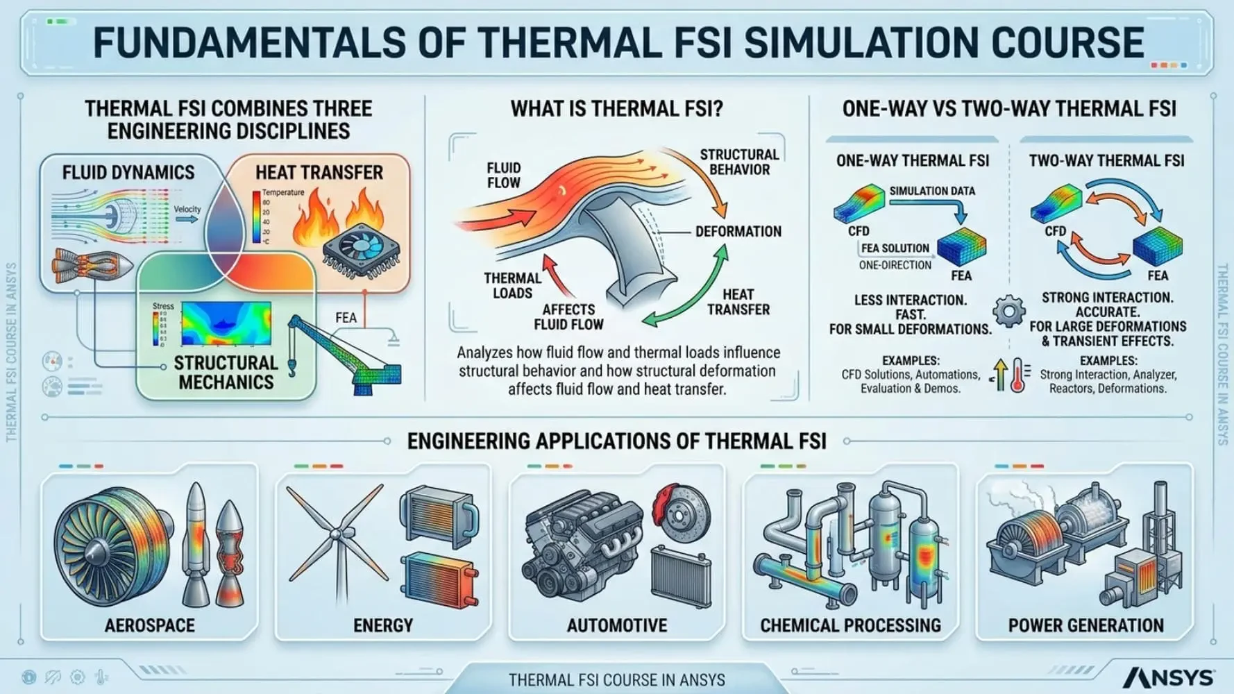
Thermal FSI combines three engineering disciplines:
Fluid Dynamics
Heat Transfer
Structural Mechanics
What is Thermal FSI?
Thermal Fluid-Structure Interaction analyzes how fluid flow and thermal loads influence structural behavior and how structural deformation affects fluid flow and heat transfer.
One-Way vs Two-Way Thermal FSI
Learn the differences between:
One-Way Thermal FSI
Two-Way Thermal FSI
and understand when each approach is appropriate for engineering applications.
Engineering Applications of Thermal FSI
Explore how Thermal FSI is used in aerospace, energy, automotive, chemical processing, and power generation industries.
Extrinsic Thermal FSI Using System Coupling
One of the most powerful approaches to Thermal FSI involves coupling multiple ANSYS solvers.
System Coupling Fundamentals
Understand how fluid, thermal, and structural solvers exchange information during simulation.
Data Transfer Between Solvers
Learn how temperature, pressure, displacement, and stress fields are transferred across interfaces.
Advantages of External Coupling
Discover situations where System Coupling provides superior accuracy and flexibility.
Intrinsic Thermal FSI Inside Fluent
Recent developments allow Thermal FSI calculations directly within the Fluent environment.
Structure Model Fundamentals
Learn how the integrated structural solver works inside Fluent.
Fully Coupled Thermal-Structural Analysis
Perform fluid, thermal, and structural calculations without external coupling tools.
Intrinsic vs Extrinsic Thermal FSI
Compare computational cost, accuracy, workflow complexity, and engineering applicability.
Thermal FSI Analysis of Engineering Manifolds
Thermal and mechanical loads often interact within industrial manifold systems.
Two-Way Thermal FSI Simulation
Investigate mutual interaction between fluid flow and structural deformation.
Thermal Stress Evaluation
Analyze stress concentrations caused by temperature gradients and pressure loading.
Industrial Design Applications
Apply Thermal FSI techniques to realistic engineering systems.
T-Junction Thermal Fatigue and Structural Analysis
T-junctions are common locations for thermal fatigue and structural failure.
One-Way Thermal FSI Modeling
Evaluate thermal loads transferred from fluid to structure.
Thermal Mixing Effects
Study temperature fluctuations and their impact on structural integrity.
Engineering Reliability Assessment
Use simulation results to improve system durability.
Intrinsic Thermal FSI for Pipe Systems
Piping networks frequently experience thermal expansion and flow-induced loading.
Elbow and Bent Pipe Analysis
Investigate structural deformation under thermal and hydraulic loads.
Comparative Thermal FSI Studies
Compare simulations with and without thermal effects.
Structural Performance Evaluation
Assess deformation, displacement, and stress behavior.
Advanced Two-Way Thermal FSI in T-Junction Systems
Thermal-fluid interaction becomes increasingly important in complex piping systems.
Coupled Thermal and Mechanical Response
Analyze how structural deformation alters fluid behavior.
Fully Integrated Thermal FSI Workflow
Study advanced coupling techniques within a unified simulation environment.
Industrial Process Applications
Apply results to process engineering and energy systems.
Gas Turbine Thermal FSI Simulation
Gas turbines represent one of the most demanding Thermal FSI applications.
Thermal Loading on Turbine Blades
Investigate temperature-induced stresses in rotating components.
Structural Integrity Assessment
Analyze deformation and mechanical response under extreme operating conditions.
Aerospace and Energy Applications
Apply Thermal FSI methodologies to high-performance engineering systems.
Learning Thermal FSI Course in ANSYS Outcomes
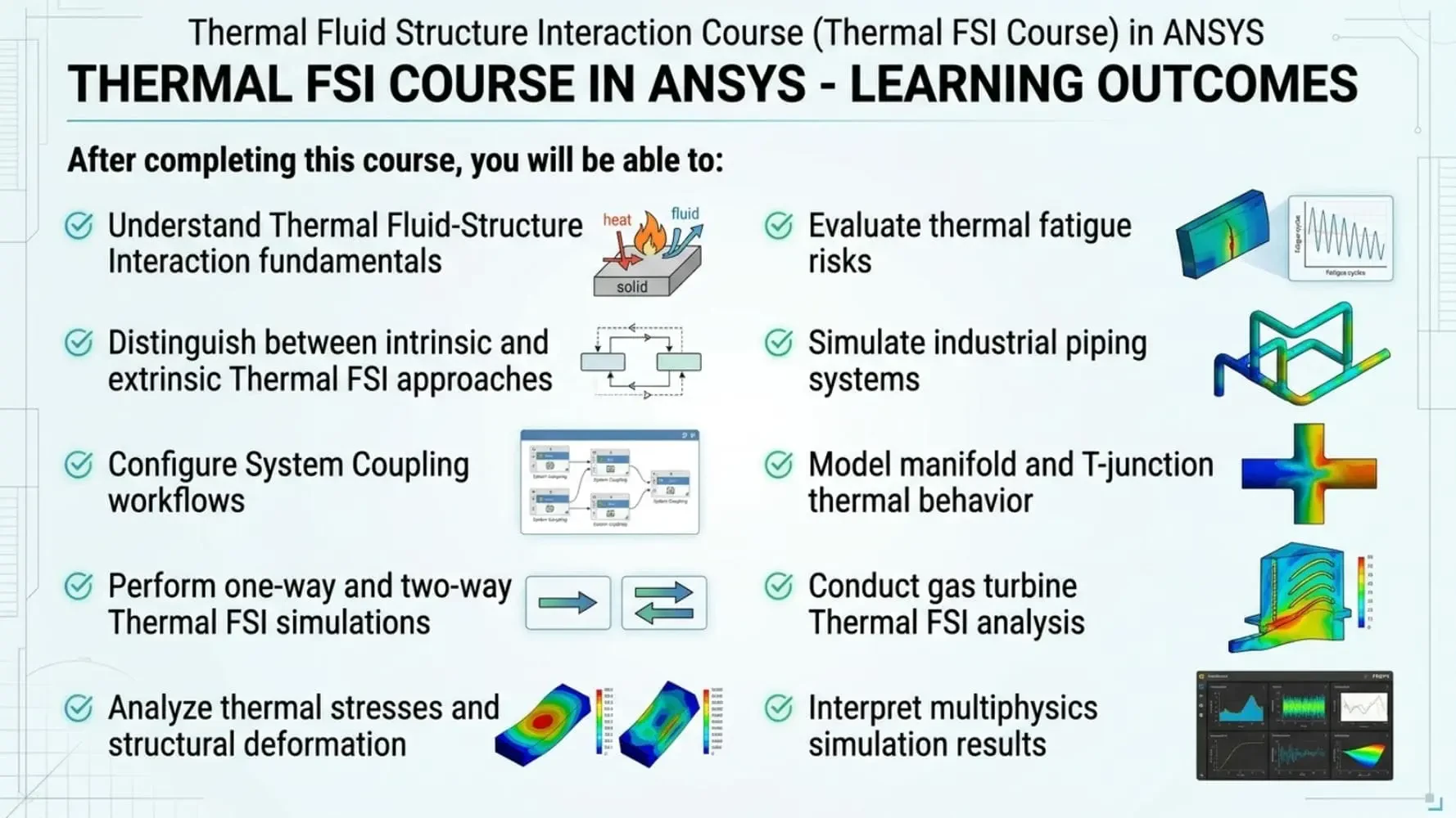
After completing this course, you will be able to:
Understand Thermal Fluid-Structure Interaction fundamentals
Distinguish between intrinsic and extrinsic Thermal FSI approaches
Configure System Coupling workflows
Perform one-way and two-way Thermal FSI simulations
Analyze thermal stresses and structural deformation
Evaluate thermal fatigue risks
Simulate industrial piping systems
Model manifold and T-junction thermal behavior
Conduct gas turbine Thermal FSI analysis
Interpret multiphysics simulation results
Technical Skills You Will Develop with Thermal Fluid-Structure Interaction Course
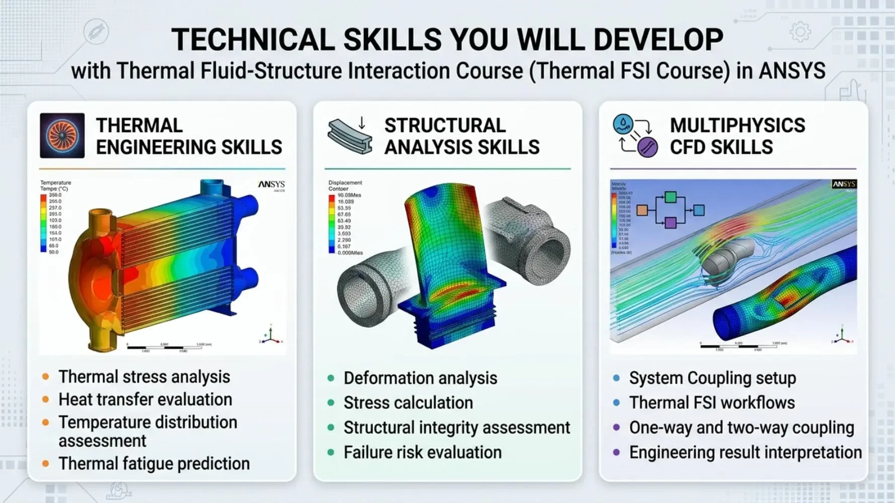
Thermal Engineering Skills
Thermal stress analysis
Heat transfer evaluation
Temperature distribution assessment
Thermal fatigue prediction
Structural Analysis Skills
Deformation analysis
Stress calculation
Structural integrity assessment
Failure risk evaluation
Multiphysics CFD Skills
System Coupling setup
Thermal FSI workflows
One-way and two-way coupling
Engineering result interpretation
Who Should Take This Course?
Mechanical Engineers
Engineers working with thermal systems, piping networks, and industrial equipment.
Aerospace Engineers
Professionals involved in turbine design, thermal protection systems, and aerospace structures.
Energy Engineers
Engineers focused on power generation and thermal equipment analysis.
CFD Engineers
Simulation specialists seeking expertise in multiphysics and coupled analyses.
Researchers and Graduate Students
Students and researchers working on thermal-fluid-structural interactions and advanced engineering simulations.
Why Learn with MR CFD?
MR CFD combines theoretical foundations with industrial engineering applications. Rather than focusing solely on software workflows, this course teaches how Thermal FSI is used to solve real-world engineering challenges involving fluid flow, heat transfer, and structural response.
Integrated with other specialized CFD Courses, this training provides a complete pathway toward expertise in thermal-structural coupling, thermal stress analysis, and advanced multiphysics simulations.
Master Thermal Fluid-Structure Interaction for Real Engineering Applications
Modern engineering systems rarely operate under purely fluid or structural conditions. Thermal loads, fluid forces, and structural deformation interact continuously and must be analyzed together to achieve reliable designs.
Enroll in the Thermal Fluid-Structure Interaction (Thermal FSI) in ANSYS course and develop professional skills in thermal stress analysis, coupled multiphysics simulation, fluid-solid interaction, and advanced thermal engineering applications.
Thermal FSI is a multiphysics simulation approach that simultaneously analyzes fluid flow, heat transfer, and structural deformation.
Conventional FSI focuses on fluid and structural interactions, while Thermal FSI additionally includes temperature effects and thermal stresses.
One-way Thermal FSI transfers fluid and thermal loads to the structure, while two-way Thermal FSI also accounts for structural feedback on the fluid flow.
Intrinsic Thermal FSI performs fluid and structural calculations within a single solver environment without external system coupling.
Extrinsic Thermal FSI uses multiple solvers connected through System Coupling to exchange fluid, thermal, and structural data.
Aerospace, power generation, automotive, oil and gas, chemical processing, and energy industries commonly use Thermal FSI.
Yes. Thermal FSI is widely used to investigate temperature-induced stresses and thermal fatigue risks.
Yes. The course includes thermal-structural analysis of gas turbine components under realistic operating conditions.
Yes. It is specifically designed for CFD engineers, thermal engineers, structural analysts, and multiphysics researchers.
You will learn thermal stress analysis, thermal deformation prediction, System Coupling workflows, one-way and two-way Thermal FSI, and advanced multiphysics engineering simulations.