

Francis Turbine, ANSYS Fluent CFD Simulation Training
Price: $24
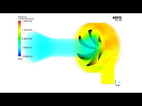
- The present problem simulates the water flow inside a Francis water turbine by ANSYS Fluent software.
- The geometry is designed using Design Modeler software.
- The meshing of the model has been done using ANSYS Meshing software and the element number is 4653160.
- Frame motion (MRF) is used to define the rotation of the blades inside the chamber.
Description
The present problem simulates the water flow inside a Francis water turbine using ANSYS Fluent software. A water turbine is turbomachinery that converts kinetic energy from water flow or potential energy from water height differences into rotational motion.
Francis turbines are one of the types of water turbines that can use kinetic and potential energy for power generation at the same time due to the location of their blades.
In this type of turbine, water flows into the volute chamber because due to the blades' circular structure, the flow of fluid colliding with the blades must be rotational to improve the system's operational efficiency. The water flow is then transferred to the turbine runner blades with a specific flow rate, and as a result, the desired work is produced by rotating these blades by the water flow.
Finally, the outflow of water from the turbine runner blades will be axial. In the present simulation, a flow of water with a flow rate of 1.996 kg/s enters the turbine's inner chamber with a rotational speed of 158 rpm for the blades.
Francis Methodology
Frame motion (MRF) defines the blades' rotation inside the chamber and creates the resulting rotational flow around the blades. It is assumed that the area of water flow around the blades has a rotational motion relative to the blades, While the rotating blades have a rotational speed of zero relative to this rotating area.
The geometry is designed using Design Modeler software. In the design of the present model, two main parts have been considered, which include fixed walls that have fixed vanes with fixed angles and moving walls that have rotating vanes.
The model meshing has been done using ANSYS Meshing software, and the mesh type is unstructured. The element number is 4653160. Also, the mesh quality is considered finer in the areas close to the blades.
Francis Conclusion
At the end of the solution process, two-dimensional and three-dimensional contours related to pressure, velocity, path lines, and velocity vectors are obtained. As it is obvious, the maximum velocity occurs near the rotating blades. Also, all the possible results can be extracted, like the pressure drop equal to 2.3 e+3.