

Fuel Injection inside a Chamber 2-D CFD Simulation
Price: $100
In this project, Injection inside a 2D Chamber with DPM has been simulated, and the results of this simulation have been investigated.
Fuel Injection inside a Chamber 2-D CFD Simulation
Price: $100
In this project, Injection inside a 2D Chamber with DPM has been simulated, and the results of this simulation have been investigated.
Fuel Injection inside a Chamber 2-D CFD Simulation, ANSYS Fluent Training
The simulation is about fuel injection in a 2D chamber via ANSYS Fluent. In this project, a two-dimensional cylindrical chamber is designed. Fuel flow from the center and airflow from the outside into the chamber.
A Discrete Phase Model must be used to define fuel injection, and an injection process must be defined from the central part of the chamber. The airflow inside the chamber is continuous, and the fuel flow enters the chamber discretely.
Thus, the solution perspective changes from Eulerian to Lagrangian by creating an interaction between discrete particles and a continuous medium. The fuel material is injected surface type in the form of inert particles and has a velocity of 1 m.s-1 and a diameter of 0.0002 m, injected in 0 s to 1 s.
To define the boundary conditions, the velocity boundary condition for airflow is used; So that air enters the chamber at a speed of 0.2 m.s-1. The modeling is unsteadily (Transient), and the time step is equivalent to 0.002 s.
Geometry & Mesh
The present geometry is designed in a 2D model via Design Modeler. The computational zone is the interior of a chamber that includes an airflow inlet and a fuel inlet.
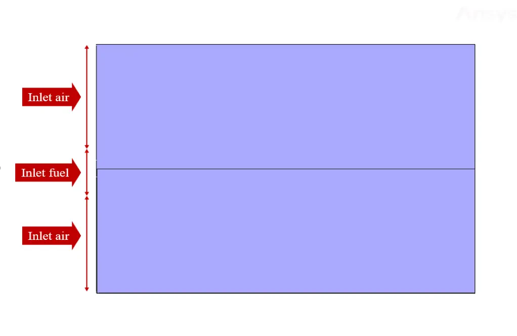
The mesh of the present model has been done via ANSYS Meshing. Mesh is structured, and the number of production cells equals 9211.
Set-up & Solution
Assumptions used in this simulation :
- Pressure-based solver is used.
- The present simulation is unsteady.
- The effect of gravity with a gravitational acceleration of 9.81 m.s-2 has been applied to the model.
| Models | ||
| Viscous | k-omega | |
| k-omega model | standard | |
| Discrete Phase Model | On | |
| number of injections | 1 | |
| injection type | surface | |
| particle type | inert | |
| Boundary conditions | ||
| Inlet (air) | Velocity Inlet | |
| velocity magnitude | 0.2 m.s-1 | |
| discrete phase BC type | escape | |
| Inlet (fuel) | Velocity Inlet | |
| velocity magnitude | 1 m.s-1 | |
| discrete phase BC type | escape | |
| Walls | Wall | |
| wall motion | stationary wall | |
| discrete phase BC type | reflect | |
| Outlet | Pressure Outlet | |
| gauge pressure | 0 pascal | |
| discrete phase BC type | escape | |
| Methods | ||
| Pressure-Velocity Coupling | Coupled | |
| pressure | PRESTO | |
| momentum | second-order upwind | |
| species fraction | second-order upwind | |
| turbulent kinetic energy | first-order upwind | |
| specific dissipation rate | first-order upwind | |
| Initialization | ||
| Initialization methods | standard | |
| gauge pressure | 0 pascal | |
| x-velocity | 0.2 m.s-1 | |
| y-velocity | 0 m.s-1 | |
Fuel Injection inside a 2D Chamber Results
After calculation, 2D contours related to velocity and pressure, and DPM concentration are obtained. The contours show that The velocity and pressure in the fuel inlet section are higher than in other zones because it is injected into the space inside the chamber at a higher speed.
Also, a particle track related to the discrete phase model has been obtained in the chamber's interior, which shows how the discrete phase is dispersed and its impact from the continuous airflow.
The simulation is performed in 2 s, and the discrete phase propagation process occurs in its initial 1 s. Thus, the discrete phase concentration contour and the discrete particle sequence show that the desired discrete particles are directed to the output port of the chamber over time.