

Heat Exchanger with Inner Fins CFD Simulation
Price: $8
The present problem is to simulate a heat exchanger using ANSYS Fluent software.
Heat Exchanger with Inner Fins CFD Simulation
Price: $8
The present problem is to simulate a heat exchanger using ANSYS Fluent software.
Heat Exchanger with Inner Fins, ANSYS Fluent CFD Simulation Training
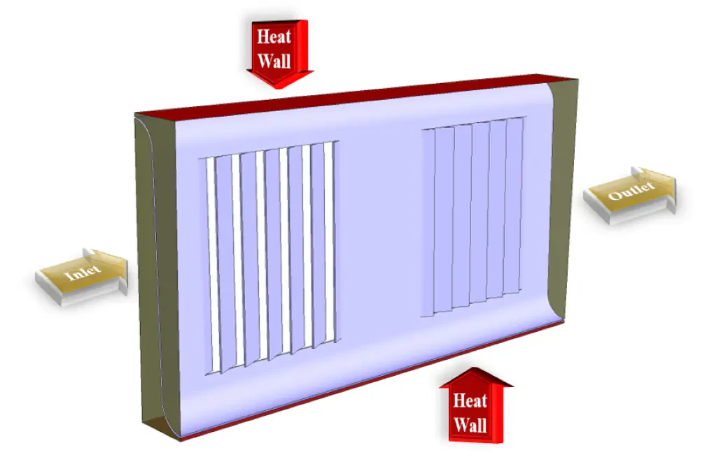
The present problem is to simulate a heat exchanger using ANSYS Fluent software. In this simulation, airflow enters the device at a velocity of 22 m.s-1 and a temperature of 313 K and exits the exchanger at a pressure equal to atmospheric pressure. For the operating mechanism of the device, it is assumed that the upper and lower surfaces of the device have a thermal boundary condition of the constant temperature type equivalent to a temperature of 323 K. Also, a curved central wall in this device with several rows of blades and fins is designed to help better airflow and better heat transfer.
This work aims to investigate the effect of high-temperature walls on the airflow temperature through the heat exchanger's interior.
Heat Exchanger Geometry & Mesh
The present model is designed in three dimensions using Design Modeler software. The model includes a heat exchanger with dimensions of 0.0018 m, 0.0082 m, and 0.0162 m; So that its inlet and outlet ducts are on both sides, and a curved inner wall with several rows of fins is located inside it, and its upper and lower walls are distinguished as surfaces with temperature condition.
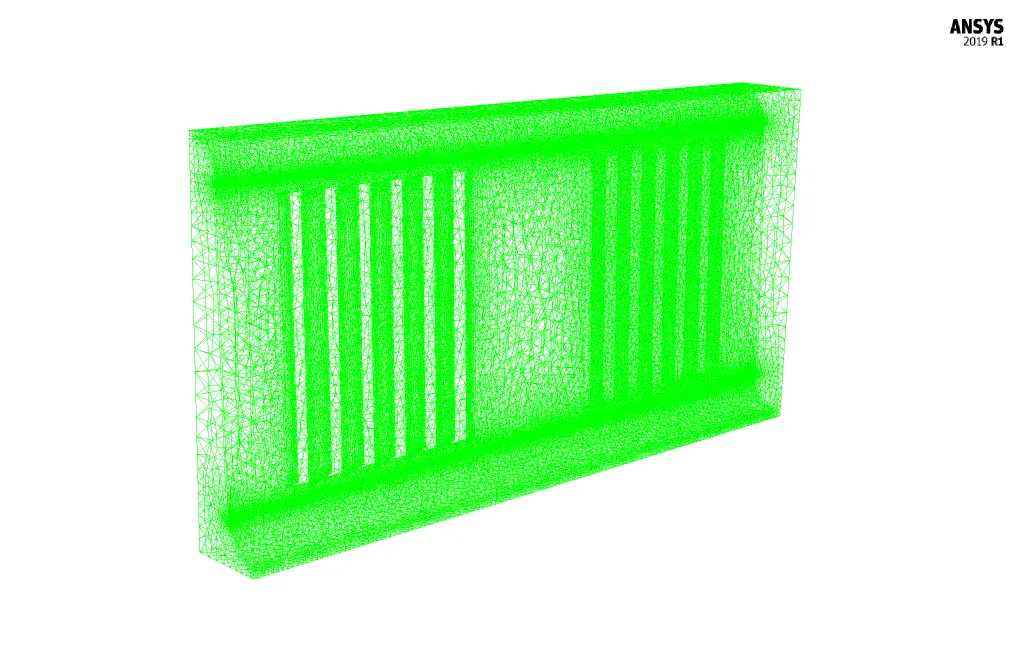
We carry out the meshing of the model using ANSYS Meshing software, and the mesh type is unstructured. The element number is 2039783. The following figure shows the mesh.
Heat Exchanger CFD Simulation
We consider several assumptions to simulate the present model:
- We perform a pressure-based solver.
- The simulation is steady.
- The gravity effect on the fluid is ignored.
The following table represents a summary of the defining steps of the problem and its solution:
| Models (Heat Exchanger) | ||
| Viscous | k-epsilon | |
| k-epsilon model | standard | |
| near wall treatment | standard wall function | |
| Energy | On | |
| Boundary conditions (Heat Exchanger) | ||
| Inlet | Velocity Inlet | |
| velocity magnitude | 22 m.s-1 | |
| temperature | 313 K | |
| Outlet | Pressure Outlet | |
| gauge pressure | 0 Pascal | |
| Solid Wall | (CFD Simulation) | Wall |
| wall motion | stationary wall | |
| heat flux | 0 W.m-2 | |
| Heat Wall | Wall | |
| wall motion | stationary wall | |
| temperature | 323 K | |
| Methods (Heat Exchanger) | ||
| Pressure-Velocity Coupling | SIMPLE | |
| Pressure | second order | |
| momentum | second order upwind | |
| turbulent kinetic energy | first order upwind | |
| turbulent dissipation rate | first order upwind | |
| energy | second order upwind | |
| Initialization (Heat Exchanger) | ||
| Initialization methods | Standard | |
| gauge pressure | 0 pascal | |
| x-velocity & y-velocity | 0 m.s-1 | |
| z-velocity | 22 m.s-1 | |
| temperature | 313 K | |
Results
At the end of the solving process, three-dimensional and two-dimensional contours related to pressure, velocity and temperature are obtained. The contours show that the incoming air flow to the heat exchanger is affected by the hot walls and its temperature increases.
You can obtain Geometry & Mesh file and a comprehensive Training Movie that presents how to solve the problem and extract all desired results.