
Heat Exchanger CFD Design & Performance Simulation Course (Intermediate)
Price:
$199
$149.40
Intermediate Heat Exchanger CFD Course: Execute 10 production-grade ANSYS Fluent and CFX projects covering complex thermal management systems.
Advanced Physics Modeling: Master conjugate heat transfer (CHT), nanofluid mixtures, and phase change material (PCM) latent heat simulations.
Geometric Optimization: Analyze thermal effectiveness and hydraulic losses using helical fins, baffles, and multi-stream configurations.
Diverse Configurations: Simulate plate, shell-and-tube, triple, and solar heat exchangers for renewable energy, HVAC, and process engineering sectors.
Engineering ROI: Transition from theoretical calculations to validated, simulation-driven heat exchanger design to solve real-world industrial challenges.
Solar Heat Exchanger: CFD Simulation by ANSYS Fluent
Solar Heat Exchanger CFD Simulation: Radiation and Thermal Performance Analysis A comprehensive computational fluid dynamics investigation of a specialized solar heat exchanger design featuring an absorber plate, internal flow barriers, and dual-medium heat transfer. This simulation captures the complex interplay between solar radiation, conduction, and convection mechanisms to demonstrate the thermal performance characteristics of this renewable energy system. Solar Heat Exchanger Design and Operating Principles This simulation examines a specialized heat exchanger designed to capture and transfer solar thermal energy to a working fluid. The system incorporates an innovative dual-medium approach with an air gap and absorber plate to maximize solar energy capture and transfer to the water flow through strategic internal flow barriers. System Configuration Primary Components: Solar absorber plate exposed to radiation Air gap between front plate and absorber Water flow channel with internal flow barriers Strategic internal walls for flow path extension Heat Transfer Pathway: Solar radiation absorption at absorber plate Air gap heating through radiation and convection Conduction through absorber plate Convective transfer to water flow Geometric Specifications Flow Path Design: Extended water flow route via internal barriers Absorber Orientation: Positioned for maximum solar radiation capture Internal Barriers: Multiple rows of flow obstacles for extended fluid residence time Air Gap Configuration: Optimized spacing for thermal performance Computational Approach and Radiation Modeling Mesh Characteristics Grid Type: Unstructured mesh generated in ANSYS Meshing Cell Count: 304,200 elements Resolution Focus: Enhanced density near absorber plate and internal barriers Quality Parameters: Optimized for complex geometry with multiple domains Radiation Modeling Strategy Primary Model: Discrete Ordinates (DO) radiation model Model Capabilities: Handles scattering media Accounts for semi-transparent boundaries Manages specular surfaces Supports wavelength-dependent transmission Solar Loading: Solar Ray Tracing model implementation Solar Parameters: Direct solar radiation: 1150 W/m² Diffuse solar radiation: 80 W/m² Incidence angle: Perpendicular to absorber plane Operating Conditions Water Flow: 4 m/s inlet velocity at 30°C Outlet Condition: Atmospheric pressure Air Gap: Natural convection and radiation heat transfer Thermal Boundaries: Solar radiation on absorber surface Results and Performance Analysis Thermal Characteristics Temperature Distribution: Visualization of thermal gradients throughout the system Heat Transfer Pathways: Identification of primary energy transfer routes Absorber Performance: Temperature profile across the solar collector surface Water Temperature Gain: Progressive heating along the extended flow path Flow Behavior Velocity Patterns: Analysis of flow development around internal barriers Pressure Distribution: Characterization of pressure drop across the exchanger Recirculation Zones: Identification of potential thermal mixing regions Barrier Effectiveness: Assessment of flow path extension and residence time Radiation Effects Absorption Patterns: Distribution of captured solar energy across absorber Air Gap Thermal Gradient: Temperature stratification in the front air layer Direct vs. Diffuse Contribution: Relative impact of radiation components Thermal Losses: Evaluation of energy not transferred to working fluid Performance Metrics Overall Efficiency: Ratio of captured energy to incident solar radiation Temperature Rise: Quantification of water temperature increase Heat Transfer Rate: Total thermal energy transferred to water flow Pressure Drop: Hydraulic resistance through the extended flow path Engineering Insights Design Optimization: Guidance for barrier placement and configuration Performance Enhancement: Strategies for improving solar absorption and transfer Operational Parameters: Effects of flow rate on thermal efficiency System Scalability: Considerations for larger implementation This detailed CFD simulation provides valuable insights into the thermal-hydraulic behavior of this specialized solar heat exchanger design. The results demonstrate the effectiveness of combining strategic flow path extension with optimized solar absorption to achieve efficient thermal energy capture and transfer. The comprehensive radiation modeling approach ensures accurate representation of the complex heat transfer mechanisms involved in solar thermal systems, providing reliable guidance for design optimization and performance prediction in renewable energy applications.
Heat Exchanger CFD Design & Performance Simulation Course (Intermediate)
Price:
$199
$149.40
Intermediate Heat Exchanger CFD Course: Execute 10 production-grade ANSYS Fluent and CFX projects covering complex thermal management systems.
Advanced Physics Modeling: Master conjugate heat transfer (CHT), nanofluid mixtures, and phase change material (PCM) latent heat simulations.
Geometric Optimization: Analyze thermal effectiveness and hydraulic losses using helical fins, baffles, and multi-stream configurations.
Diverse Configurations: Simulate plate, shell-and-tube, triple, and solar heat exchangers for renewable energy, HVAC, and process engineering sectors.
Engineering ROI: Transition from theoretical calculations to validated, simulation-driven heat exchanger design to solve real-world industrial challenges.
-
Section 1
Traditional Heat Exchanger Configurations
-
Triple Heat Exchanger, CFD Simulation Ansys Fluent Training An in-depth computational fluid dynamics analysis of a triple concentric tube heat exchanger, exploring the complex thermal interactions between three fluid streams flowing through concentrically arranged pipes. This project demonstrates complete simulation workflow from geometry creation through results interpretation, providing valuable insights into advanced heat exchanger performance. Project Overview This simulation investigates a triple concentric tube heat exchanger (TCTHE), an enhanced design that improves upon traditional double-pipe configurations by adding an intermediate tube. The model features three distinct flow channels with different temperature fluids, creating multiple heat transfer interfaces within a compact arrangement. Key Simulation Parameters Geometry: Three-dimensional concentric tubes modeled in ANSYS DesignModeler Mesh: 1.96 million elements generated using ANSYS Meshing Flow Conditions: Laminar flow regime for all domains Thermal Conditions: Temperature differentials between all three fluid streams Methodology and Approach Geometric Configuration The heat exchanger consists of three concentrically arranged tubes creating separate flow paths: Inner tube: Water at 280K with 0.1 kg/s mass flow rate Middle annulus: Water at 330K with 0.05 kg/s mass flow rate Outer annulus: Water at 290K with 0.05 m/s inlet velocity Simulation Setup Laminar flow model implementation Energy equation activation for thermal analysis Appropriate boundary conditions at inlets, outlets, and walls Interface definitions for thermal interactions between domains Solution Strategy Sequential solving of flow and energy equations Convergence monitoring for momentum and thermal residuals Post-processing of temperature fields and heat transfer metrics Results and Analysis Temperature Distribution The simulation reveals comprehensive temperature patterns showing: Gradual cooling of the middle hot stream along the exchanger length Simultaneous heating of both inner and outer fluid streams Complex thermal gradients at the interfaces between domains Heat Transfer Performance Quantification of heat exchange between each pair of fluid streams Analysis of local and overall heat transfer coefficients Effectiveness evaluation compared to conventional designs Engineering Insights Demonstration of the TCTHE’s ability to facilitate simultaneous heat exchange between multiple fluid streams Identification of thermal performance characteristics specific to triple concentric arrangements Practical considerations for design optimization and operational parameters Learning Outcomes This project provides practical experience in: Modeling complex multi-domain heat exchanger geometries Configuring multi-stream heat transfer simulations Analyzing thermal interactions between multiple fluid domains Evaluating performance metrics for advanced heat exchanger designs The simulation techniques demonstrated are applicable to various thermal management challenges across process industries, HVAC systems, and energy recovery applications.
Lesson 1 12m 18s -
Plate Heat Exchanger CFD Simulation by ANSYS Fluent Training A comprehensive computational fluid dynamics analysis of a 4-layer plate heat exchanger design, demonstrating the thermal-hydraulic performance characteristics and heat transfer mechanisms between alternating hot and cold fluid channels. This simulation provides valuable insights into plate heat exchanger behavior through detailed visualization of temperature distributions, flow patterns, and quantitative performance metrics. Project Overview This simulation investigates a 4-layer plate heat exchanger configuration with alternating hot and cold water channels. The model captures the complex fluid flow and heat transfer phenomena occurring within the compact plate arrangement, demonstrating how thermal energy is effectively transferred between the fluid streams through the separating plates. Key Simulation Parameters Configuration: 4-layer plate heat exchanger with alternating hot and cold channels Hot Fluid: Water at 286.2K with 0.0045 kg/s mass flow rate Cold Fluid: Water at 276.5K with 0.00361 kg/s mass flow rate Mesh: Unstructured grid with approximately 2,273,000 elements Methodology and Approach Geometric Configuration The heat exchanger consists of four parallel flow channels arranged in alternating hot and cold layers: Layers 1 and 3: Cold fluid channels (heating process) Layers 2 and 4: Hot fluid channels (cooling process) Defined inlet and outlet regions for each fluid stream Solid plates separating fluid channels (not explicitly mentioned but implied) Simulation Setup Solver Configuration: Pressure-based, steady-state simulation Turbulence Model: Standard k-epsilon with standard wall functions Energy Equation: Enabled for heat transfer analysis Discretization Schemes: Momentum: Second-order upwind Energy: Second-order upwind Turbulence parameters: First-order upwind Solution Algorithm: SIMPLE pressure-velocity coupling Boundary Conditions Hot Inlet: 286.2K at 0.0045 kg/s with 2% turbulence intensity Cold Inlet: 276.5K at 0.00361 kg/s with 2% turbulence intensity Hydraulic Diameter: 0.003m for both inlets Initialization Parameters: Zero gauge pressure, specified velocity components and turbulence parameters Results and Analysis Temperature Distribution The simulation reveals the thermal behavior across all four layers: Progressive temperature change along the flow path in each channel Hot fluid cooling from 286.2K to 281.213K Cold fluid heating from 276.5K to 282.725K Temperature convergence at exits (~282K for both streams) Flow Characteristics Detailed velocity contours showing flow distribution within each layer Streamline visualizations demonstrating flow patterns and potential recirculation zones Impact of plate geometry on local flow behavior Heat Transfer Performance Quantified heat transfer rate from hot fluid: 93.8503W Quantified heat absorption by cold fluid: 93.9754W Energy balance verification with less than 0.2% discrepancy Thermal effectiveness assessment based on inlet-outlet temperature differences Engineering Insights The simulation demonstrates several key aspects of plate heat exchanger performance: Effective thermal energy transfer between alternating fluid streams Nearly identical exit temperatures despite different inlet conditions Balanced heat transfer rates confirming simulation accuracy Influence of flow distribution on local heat transfer effectiveness This analysis provides valuable information for design optimization, performance prediction, and operational parameter selection for plate heat exchangers in various industrial applications including HVAC systems, food processing, and chemical industries.
Lesson 2 15m 24s
-
-
Section 2
Advanced Shell and Tube Designs
$119.40-
Baffle Cut Effect on Shell and Tube Heat Exchanger Efficiency, Conjugated Heat Transfer A detailed computational fluid dynamics investigation into the influence of baffle configuration on shell and tube heat exchanger performance, with specific focus on conjugated heat transfer effects. This study examines the complex relationship between thermal enhancement and hydraulic penalties associated with baffle implementation, providing valuable design insights for optimizing heat exchanger efficiency. Heat Exchanger Configuration and Design Parameters This simulation explores a shell and tube heat exchanger featuring aluminum baffles with a 36% cut ratio. The model incorporates conjugated heat transfer to accurately capture the thermal interaction between fluid domains and solid baffle structures, demonstrating how baffle thermal conductivity contributes to overall heat transfer enhancement. Geometric Specifications Shell Dimensions: 600mm length, 90mm diameter Tube Arrangement: 7 tubes in triangular pattern, 20mm outer diameter Tube Spacing: 30mm center-to-center distance Baffle Configuration: 6 baffles with 4mm thickness Baffle Spacing: 86mm center-to-center distance Baffle Cut Ratio: 36% of shell diameter Simulation Setup Mesh: Unstructured grid with 1,953,754 elements Near-Wall Treatment: Boundary layer mesh for appropriate y+ values Flow Conditions: Water at 300K entering shell side at 0.5 kg/m³ Thermal Boundary: Constant tube wall temperature of 450K Methodology and Physical Models Material Properties Working Fluid: Water with temperature-dependent properties Property Definition: Piecewise-linear functions for density, viscosity, specific heat, and thermal conductivity Baffle Material: Aluminum with high thermal conductivity Numerical Approach Solver Type: Pressure-based, steady-state simulation Turbulence Model: Realizable k-ε with standard wall functions Solution Algorithm: SIMPLE pressure-velocity coupling Discretization: First-order upwind schemes for momentum, energy, and turbulence parameters Initialization: Standard method with -0.7 m/s inlet velocity Boundary Conditions Shell Inlet: Mass flow inlet at 300K Shell Outlet: Zero gauge pressure outlet Shell Wall: Adiabatic condition (zero heat flux) Tube Walls: Constant temperature at 450K Baffles: Solid aluminum with conjugated heat transfer Results and Performance Analysis Thermal Performance Exit Temperature: Shell-side fluid heated to approximately 360K Temperature Rise: 60K increase from inlet to outlet Heat Transfer Enhancement: Accelerated temperature diffusion due to baffle thermal conductivity Heat Transfer Coefficient: Convergence demonstrated with increasing iterations Flow Characteristics Flow Pattern: Complex cross-flow arrangement induced by baffles Pressure Drop: Approximately 1 kPa across the heat exchanger Velocity Distribution: Increased local velocities in baffle-restricted regions Conjugated Heat Transfer Effects Baffle Thermal Contribution: Enhanced temperature distribution through conductive heat paths Thermal Gradients: Visualization of temperature fields across fluid and solid domains Heat Transfer Mechanism: Combined convective and conductive pathways through strategic baffle placement Engineering Implications Performance Trade-offs: Balance between thermal enhancement and hydraulic penalties Design Optimization: Insights into optimal baffle cut ratio and spacing Efficiency Considerations: Improved understanding of how baffle configuration affects overall heat exchanger performance This comprehensive simulation demonstrates the significant impact of baffle design parameters on shell and tube heat exchanger efficiency, providing valuable guidance for thermal system designers seeking to optimize heat transfer performance while managing pressure drop constraints.
Lesson 1 19m 51s -
Shell and Tube Heat Exchanger with Baffle Cut and Mixture Nano Fluid by ANSYS Fluent A sophisticated computational fluid dynamics investigation exploring the combined effects of baffle configuration and nanofluid application on shell and tube heat exchanger performance. This simulation demonstrates how thermal enhancement strategies can be synergistically implemented to achieve superior heat transfer characteristics while maintaining acceptable hydraulic performance. Nanofluid Enhancement in Heat Exchanger Applications This simulation examines a shell and tube heat exchanger incorporating two advanced heat transfer enhancement techniques: strategic baffle placement and Al₂O₃-water nanofluid as the working medium. The study demonstrates how nanofluids can significantly improve thermal performance through increased effective thermal conductivity, while baffles create beneficial flow patterns that further enhance heat transfer capabilities. Performance Enhancement Mechanisms Nanofluid Benefits: Increased thermal conductivity without significant viscosity penalties Baffle Configuration: Improved shell-side flow distribution and extended flow path Combined Effects: Synergistic enhancement through complementary thermal improvement strategies Geometric Configuration and Model Parameters Heat Exchanger Specifications Shell Dimensions: 1m diameter, 4.5m length Shell-Side Fluid: Al₂O₃-water nanofluid (cold stream) Tube-Side Fluid: Water (hot stream) Baffle Arrangement: 4 baffles with 0.7m length Tube Configuration: 0.15m diameter tubes with 3m active length Connection Nozzles: 0.15m shell-side, 0.3m tube-side Computational Domain Mesh Structure: 450,980 elements generated in ANSYS Meshing Domain Regions: Shell-side flow path with baffles, tube-side flow path, solid tube walls Interface Definitions: Fluid-solid interfaces for conjugated heat transfer Simulation Methodology and Approach Multiphase Modeling Strategy Model Selection: Mixture model for nanofluid simulation Phase Definition: Water as continuous phase, Al₂O₃ particles as dispersed phase Interaction Mechanisms: Interphase drag, particle distribution, and thermal effects Numerical Methods Solver Configuration: Pressure-based coupled solver Discretization: Second-order schemes for improved accuracy Turbulence Model: k-ε model with standard wall functions Solution Process: Steady-state simulation with appropriate convergence criteria Material Properties Nanoparticles: Al₂O₃ with 40 W/m·K thermal conductivity, 3970 kg/m³ density Base Fluid: Water with standard thermophysical properties Effective Properties: Calculated based on mixture theory and particle concentration Temperature Dependence: Constant properties assumed for this simulation Results and Performance Analysis Thermal Performance Characteristics Temperature Distribution: Visualized through contours showing thermal gradients Heat Transfer Enhancement: Quantification of improvement over conventional fluids Nanofluid Effectiveness: Analysis of thermal conductivity enhancement contribution Flow Pattern Visualization Streamline Analysis: Path lines demonstrating complex flow patterns induced by baffles Recirculation Zones: Identification of mixing regions promoting heat transfer Velocity Distribution: Examination of flow acceleration in baffle-restricted areas Engineering Implications Design Considerations: Guidance for optimal baffle placement with nanofluids Performance Optimization: Balance between thermal enhancement and pumping power Practical Implementation: Insights into nanofluid concentration effects and stability requirements This comprehensive simulation provides valuable insights into the combined thermal enhancement potential of baffles and nanofluids in shell and tube heat exchangers. The results demonstrate how strategic integration of multiple enhancement techniques can achieve superior thermal performance beyond what either approach could accomplish independently, offering promising directions for heat exchanger design optimization in various industrial applications.
Lesson 2 15m 40s
-
-
Section 3
Phase Change Material Applications
$119.40-
PCM in Shell and Tube Finned Heat Exchanger Simulation A comprehensive computational fluid dynamics investigation of thermal energy storage using phase change materials (PCMs) within a finned shell and tube heat exchanger configuration. This simulation captures the complex transient behavior of PCM melting processes, demonstrating the effectiveness of latent heat storage systems for thermal management applications. Thermal Energy Storage with Phase Change Materials This simulation explores the dynamic thermal behavior of a shell and tube heat exchanger incorporating phase change materials as the storage medium. The study focuses on capturing the complex phase transformation process and associated heat transfer mechanisms that make PCMs valuable for thermal energy storage applications. PCM Operating Principles Energy Storage Mechanism: Latent heat absorption during solid-to-liquid phase transition Energy Release Process: Heat dissipation during liquid-to-solid phase change Application Versatility: Thermal regulation in both heating and cooling systems Diurnal Cycle Utilization: Heat absorption during daytime and release during nighttime Geometric Configuration and System Design Heat Exchanger Architecture Shell Design: Cylindrical tank containing uniformly distributed PCM Heat Transfer Elements: Copper tube with winding path through PCM medium Enhancement Features: Cross-shaped copper fins along tube pathway Material Selection: Copper components for high thermal conductivity Tube Specifications: 0.001m wall thickness for efficient heat transfer Computational Domain Mesh Characteristics: Unstructured grid with 2,448,380 elements Domain Regions: PCM volume, copper tube, copper fins, fluid flow path Boundary Definition: Interfaces between different materials and phases Simulation Methodology and Physical Models Phase Change Modeling Approach Model Selection: Solidification and Melting model for phase transition simulation Phase Transition Parameters: Solidus temperature: 314.15K Liquidus temperature: 317.15K Latent heat of fusion: 255,000 J/kg Material Properties PCM Characteristics: Paraffin with following properties: Density: 750 kg/m³ Specific heat capacity: 2000 J/kg·K Thermal conductivity: 0.2 W/m·K Viscosity: 0.008 kg/m·s Heat Transfer Fluid: Water at 325.15K with 1.4973 kg/s mass flow rate Structural Components: Copper tubes and fins with high thermal conductivity Numerical Approach Simulation Type: Transient analysis with 1200-second duration Time Step Configuration: Appropriate stepping for phase change capture Convergence Criteria: Suitable tolerances for energy and phase equations Results and Performance Analysis Thermal Evolution and Phase Transition Temperature Distribution: Visualization of thermal gradients throughout the storage medium Melting Front Progression: Tracking of solid-liquid interface movement over time Liquid Fraction Development: Quantification of PCM melting as a function of time Heat Transfer Effectiveness: Analysis of temperature rise near tube surfaces System Performance Metrics Energy Storage Capacity: Evaluation of total thermal energy absorbed by PCM Charging Rate: Assessment of system response to heat input Thermal Gradients: Identification of temperature distribution patterns Fin Effectiveness: Contribution of extended surfaces to overall heat transfer Engineering Insights Design Optimization: Guidance for fin placement and tube routing Operational Parameters: Influence of flow rate and inlet temperature System Response: Transient behavior during charging cycle Efficiency Considerations: Balance between thermal performance and material usage This detailed simulation provides valuable insights into the dynamic behavior of PCM-based thermal energy storage systems, demonstrating how finned shell and tube configurations can effectively manage the inherent thermal conductivity limitations of phase change materials. The results highlight the potential of such systems for applications requiring efficient thermal energy storage and release cycles, including building climate control, solar thermal systems, and waste heat recovery.
Lesson 1 19m 23s -
PCM in Three-Layer Tube Heat Exchanger Simulation A detailed computational fluid dynamics analysis of thermal energy storage using Erythritol phase change material (PCM) in a three-layer tube heat exchanger with copper fins. This simulation captures the complex phase transition dynamics and heat transfer mechanisms over an extended time period, demonstrating the effectiveness of PCM systems for thermal energy management applications. Phase Change Material for Thermal Energy Storage This simulation investigates the thermal behavior and phase transition dynamics of Erythritol PCM embedded in a three-layer tube heat exchanger. The study demonstrates how PCMs can effectively store and release thermal energy through latent heat mechanisms, providing valuable insights into their application for sustainable energy management. PCM Working Principles Energy Storage Mechanism: Latent heat absorption during solid-to-liquid transition Energy Release Process: Heat dissipation during liquid-to-solid transformation Thermal Regulation: Temperature stabilization through phase change properties Diurnal Applications: Solar energy capture during day and release during night Heat Exchanger Design and Configuration System Architecture Exchanger Type: Three-layer tube heat exchanger with enhanced surfaces Material Selection: Copper tubes and fins for superior thermal conductivity PCM Medium: Erythritol as the phase change material in storage layer Heat Transfer Fluid: Liquid silicone circulating through inner tube Enhancement Features: Copper fins for improved thermal conductance Computational Domain Mesh Characteristics: Hybrid structured/unstructured grid with 107,718 elements Domain Components: Inner tube flow path, copper tube walls, fins, PCM region Boundary Interfaces: Coupled wall conditions between different materials Simulation Methodology and Physical Models Phase Change Modeling Approach Model Selection: Solidification and Melting module for phase transition simulation Simulation Duration: Extended 12,000-second analysis to capture complete phase dynamics Time Step Configuration: Appropriate stepping for phase change resolution Material Properties and Parameters PCM Characteristics: Erythritol with defined: Solidus and liquidus temperatures Latent heat of fusion Density, specific heat, and thermal conductivity Heat Transfer Fluid: Liquid silicone at 343.15K with 1 m/s inlet velocity Structural Components: Copper with high thermal conductivity for tubes and fins Boundary Conditions Inlet Conditions: 1 m/s velocity, 343.15K temperature for silicone fluid Outer Walls: Adiabatic condition (zero heat flux) Inner Walls: Automatically coupled thermal interfaces Initial Conditions: Starting temperature and phase distribution Results and Performance Analysis Thermal Evolution and Phase Dynamics Temperature Distribution: Visualization of thermal gradients throughout the PCM medium Phase Front Progression: Tracking of solid-liquid interface movement over time Liquid Fraction Development: Quantification of PCM melting progression Heat Transfer Pathways: Analysis of conduction through fins and convection in liquid regions Performance Characteristics Energy Storage Capacity: Evaluation of thermal energy absorbed as latent heat System Response: Transient behavior during the charging cycle Fin Effectiveness: Impact of extended surfaces on heat transfer enhancement Thermal Penetration: Heat distribution patterns from tube surface into PCM volume Engineering Insights Design Considerations: Optimization guidance for fin geometry and spacing Operational Parameters: Influence of flow rate and inlet temperature System Efficiency: Balance between thermal performance and material utilization Application Potential: Suitability for various thermal management scenarios This comprehensive simulation provides valuable insights into the behavior of PCM-based thermal energy storage systems, highlighting the critical role of enhanced heat transfer surfaces in overcoming the inherent thermal conductivity limitations of phase change materials. The results demonstrate the effectiveness of copper fins in accelerating the charging process and improving overall system performance, offering practical design guidance for thermal energy storage applications ranging from building climate control to industrial waste heat recovery systems.
Lesson 2 27m 44s
-
-
Section 4
Advanced Physics and Alternative Methods
$89.40-
Plate Heat Exchanger CFD Simulation: Viscous Heating and Conjugated Heat Transfer A comprehensive computational fluid dynamics analysis of a novel plate heat exchanger design incorporating parallel solid plates with corner-mounted flow channels. This simulation captures the complex interplay between convective and conductive heat transfer mechanisms, demonstrating the unique thermal characteristics of this unconventional heat exchanger configuration. Heat Exchanger Configuration and Design Approach This simulation investigates a specialized plate heat exchanger design featuring four solid plates with integrated corner pipes, creating a unique thermal pathway that differs from conventional plate heat exchanger configurations. The study demonstrates how this arrangement facilitates heat transfer through a combination of convection in the fluid channels and conduction through the solid plates. Geometric Specifications Plate Dimensions: 2m × 2m with 0.2m thickness Flow Channels: Four corner-mounted pipes with 0.2m diameter and 1.1m length Material Configuration: Single-part solid construction with integrated flow passages Flow Arrangement: Counter-flow configuration with opposing inlet locations Computational Domain Mesh Structure: Unstructured grid with 2,216,379 elements Domain Components: Solid plates, fluid channels, fluid-solid interfaces Discretization Quality: Refined mesh near fluid-solid boundaries for accurate CHT modeling Simulation Methodology and Physical Models Conjugated Heat Transfer Approach Heat Transfer Mechanisms: Simultaneous modeling of: Convection between fluid and pipe walls Conduction through solid plates Thermal interface coupling between domains Solution Strategy: Pressure-based solver for incompressible flow Analysis Type: Steady-state simulation with coupled energy equation Operating Conditions Working Fluid: Water with temperature-dependent properties Flow Parameters: Equal velocity in all channels Temperature Differential: 20°C and 40°C inlet temperatures in counter-flow arrangement Boundary Conditions: Specified velocity inlets and pressure outlets Simplifications: Negligible gravitational effects Modeling Considerations Viscous Heating: Inclusion of energy dissipation due to fluid friction Turbulence Model: Appropriate model for pipe flow conditions Material Properties: Temperature-dependent thermal properties for water Interface Treatment: Continuous temperature and heat flux at fluid-solid boundaries Results and Performance Analysis Thermal Characteristics Temperature Distribution: Visualization of thermal gradients across solid plates Heat Transfer Pathways: Identification of primary conduction paths between channels Thermal Spreading: Analysis of heat diffusion through solid medium Temperature Profiles: Examination of fluid temperature evolution along flow paths Flow Behavior Pressure Distribution: Characterization of pressure gradients in flow channels Velocity Patterns: Analysis of flow development in pipe sections Turbulence Characteristics: Evaluation of turbulent kinetic energy distribution Viscous Effects: Assessment of viscous heating contribution to thermal performance Performance Metrics Heat Transfer Effectiveness: Evaluation of overall thermal efficiency Temperature Approach: Analysis of terminal temperature differences Pressure Drop: Quantification of hydraulic resistance Flow Distribution: Assessment of flow uniformity across channels Engineering Insights Design Implications: Guidance for optimizing plate thickness and channel placement Performance Enhancement: Strategies for improving thermal effectiveness Material Selection: Impact of solid thermal conductivity on overall performance Operational Considerations: Effects of flow rate on heat transfer characteristics This detailed simulation provides valuable insights into the thermal-hydraulic behavior of this unconventional plate heat exchanger design. The results demonstrate how the combination of strategic channel placement and solid conduction pathways can create effective heat transfer between fluid streams, offering design guidance for specialized heat transfer applications where traditional plate heat exchanger configurations may not be suitable.
Lesson 1 13m 37s -
Plate Heat Exchanger CFD Simulation with ANSYS CFX: Conjugated Heat Transfer Analysis A detailed computational fluid dynamics investigation of a specialized plate heat exchanger design featuring solid plates with corner-mounted flow channels. This simulation leverages ANSYS CFX to capture the complex interplay between convective and conductive heat transfer mechanisms, providing insights into thermal performance characteristics under counter-flow operating conditions. Heat Exchanger Configuration and Design Parameters This simulation examines a unique plate heat exchanger configuration consisting of four solid plates with integrated corner pipes, creating a specialized thermal pathway that combines convective heat transfer in fluid channels with conductive heat transfer through solid plates. The 2.5D modeling approach provides comprehensive insights into the thermal-hydraulic behavior of this system. Geometric Specifications Plate Dimensions: 2m × 2m with 0.1m thickness Flow Channels: Four corner-mounted pipes with 0.15m diameter and 1.1m length Material Configuration: Single-part construction with integrated solid and fluid domains Flow Arrangement: Counter-flow configuration with temperature differential of 20°C Computational Domain Mesh Characteristics: Unstructured grid with 5,096,686 elements Near-Wall Treatment: Five inflation layers within pipe regions for boundary layer resolution Domain Integration: Combined solid-fluid mesh with preserved interface continuity Mesh Quality: Enhanced resolution at critical heat transfer interfaces Simulation Methodology and Physical Models Conjugated Heat Transfer Approach Heat Transfer Mechanisms: Simultaneous modeling of: Convective transport between fluid and pipe walls Conductive diffusion through solid plates Thermal coupling at fluid-solid interfaces Energy Formulation: Thermal Energy model for incompressible flow Analysis Type: Steady-state simulation with coupled thermal-fluid solution Numerical Methods and Models Turbulence Model: k-epsilon with Scalable Wall Function Discretization Scheme: High Resolution Advection Scheme for improved accuracy Turbulence Numerics: High Resolution approach for turbulence equations Convergence Criteria: Appropriate residual targets for momentum and energy Operating Conditions Working Fluid: Water with temperature-dependent properties Flow Parameters: Uniform velocity in all channels Temperature Differential: 20°C and 40°C inlet temperatures in opposing flow directions Simplifications: Negligible gravitational effects, steady-state conditions Results and Performance Analysis Thermal Characteristics Temperature Distribution: Visualization of thermal gradients throughout the system Heat Transfer Pathways: Identification of primary conduction routes between channels Thermal Spreading: Analysis of heat diffusion patterns within solid plates Temperature Contours: Clear visualization of isothermal lines across the domain Flow Behavior Pressure Distribution: Characterization of pressure fields in flow channels Velocity Patterns: Analysis of flow development in pipe sections Turbulence Characteristics: Evaluation of turbulent kinetic energy distribution Flow Uniformity: Assessment of flow distribution across parallel channels Performance Metrics Heat Transfer Effectiveness: Evaluation of thermal exchange efficiency Temperature Profiles: Analysis of fluid temperature evolution along flow paths Pressure Drop: Quantification of hydraulic resistance through the system Thermal Gradients: Assessment of temperature differential across solid medium Engineering Insights Design Implications: Guidance for optimizing plate thickness and pipe placement Velocity Effects: Confirmation of flow rate impact on convective heat transfer Heat Path Optimization: Strategies for enhancing conductive pathways System Efficiency: Balance between thermal performance and pressure loss This comprehensive CFD simulation using ANSYS CFX provides valuable insights into the thermal-hydraulic behavior of this specialized plate heat exchanger design. The results demonstrate the effectiveness of the counter-flow arrangement and the significant role of conduction through the solid plates in facilitating heat transfer between the fluid streams. The high-resolution numerical approach with enhanced boundary layer treatment ensures accurate capture of the convective heat transfer processes, providing reliable guidance for design optimization and performance prediction in similar heat exchanger applications.
Lesson 2 1h 29m 15s
-
-
Section 5
Specialized Configurations and Applications
$119.40-
Shell and Tube Heat Exchanger with Helical Fins and Nanofluid: CFD Analysis A comprehensive computational fluid dynamics investigation of an enhanced shell and tube heat exchanger design featuring helical fins and Al₂O₃-water nanofluid as the working medium. This simulation demonstrates how geometric modifications and advanced working fluids can synergistically improve heat transfer performance in industrial heat exchange applications. Advanced Heat Exchanger Design and Enhancement Strategies This simulation examines a shell and tube heat exchanger incorporating two significant performance enhancement techniques: helical fins in the shell-side flow path and Al₂O₃-water nanofluid as the working medium. The study demonstrates how these modifications work in concert to improve thermal performance through extended flow paths and enhanced thermal properties. Enhancement Mechanisms Helical Fin Benefits: Extended flow path length, increased turbulence, and larger heat transfer surface area Nanofluid Advantages: Improved thermal conductivity without significant viscosity penalties Combined Effect: Synergistic performance enhancement through complementary mechanisms Geometric Configuration and Model Development Heat Exchanger Architecture Basic Type: Shell and tube configuration with tube bundle Enhancement Features: Helical fins installed in shell-side flow path Flow Arrangement: Counter-flow or cross-flow configuration (as specified) Fin Design: Optimized helical geometry for flow guidance and surface area extension Computational Domain Mesh Characteristics: Unstructured grid generated in ANSYS Meshing Domain Components: Shell-side volume with fins, tube bundle, fluid regions Resolution Requirements: Refined mesh near fin surfaces and tube walls Element Quality: Optimized for complex geometry with curved surfaces Simulation Methodology and Nanofluid Modeling Nanofluid Implementation Approach Modeling Strategy: Single-phase effective property method Alternative Approach: Multiphase mixture model (noted as higher computational cost) Property Calculation: Thermophysical properties derived from base fluid and nanoparticle characteristics: Effective density Modified specific heat capacity Enhanced thermal conductivity Adjusted viscosity Physical Models and Numerical Methods Flow Regime: Appropriate turbulence model for complex geometry Heat Transfer: Conjugate modeling of fluid and solid domains Discretization Schemes: Higher-order methods for improved accuracy Solution Strategy: Pressure-based solver with suitable coupling algorithm Operating Conditions Working Fluids: Al₂O₃-water nanofluid and secondary fluid (water or other) Flow Parameters: Specified inlet velocities or mass flow rates Temperature Conditions: Defined inlet temperatures for both streams Boundary Specifications: Wall conditions, inlet/outlet parameters Results and Performance Analysis Thermal Performance Characteristics Temperature Distribution: Visualization of thermal gradients throughout the exchanger Heat Transfer Enhancement: Quantification of improvement over conventional design Nanofluid Effectiveness: Analysis of thermal conductivity enhancement contribution Fin Performance: Evaluation of extended surface contribution to overall heat transfer Flow Behavior and Hydraulic Performance Velocity Patterns: Analysis of flow development and path extension due to fins Pressure Distribution: Characterization of pressure drop across the exchanger Turbulence Effects: Examination of increased mixing due to helical geometry Secondary Flows: Identification of vortex structures enhancing heat transfer Comparative Performance Metrics Heat Transfer Coefficient: Enhancement relative to standard design Pressure Drop Penalty: Assessment of increased pumping power requirements Overall Efficiency: Balance between thermal improvement and hydraulic losses Design Optimization: Insights for fin spacing, height, and pitch optimization Engineering Implications Design Considerations: Guidance for optimal fin configuration with nanofluids Performance Predictions: Expected enhancement for various operating conditions Application Suitability: Identification of ideal implementation scenarios Economic Assessment: Balance between performance gains and manufacturing complexity This detailed CFD simulation provides valuable insights into the combined thermal enhancement potential of helical fins and nanofluids in shell and tube heat exchangers. The results demonstrate how strategic integration of multiple enhancement techniques can achieve superior thermal performance beyond what either approach could accomplish independently, offering promising directions for heat exchanger design optimization in various industrial applications requiring high thermal efficiency.
Lesson 1 17m 11s -
Solar Heat Exchanger CFD Simulation: Radiation and Thermal Performance Analysis A comprehensive computational fluid dynamics investigation of a specialized solar heat exchanger design featuring an absorber plate, internal flow barriers, and dual-medium heat transfer. This simulation captures the complex interplay between solar radiation, conduction, and convection mechanisms to demonstrate the thermal performance characteristics of this renewable energy system. Solar Heat Exchanger Design and Operating Principles This simulation examines a specialized heat exchanger designed to capture and transfer solar thermal energy to a working fluid. The system incorporates an innovative dual-medium approach with an air gap and absorber plate to maximize solar energy capture and transfer to the water flow through strategic internal flow barriers. System Configuration Primary Components: Solar absorber plate exposed to radiation Air gap between front plate and absorber Water flow channel with internal flow barriers Strategic internal walls for flow path extension Heat Transfer Pathway: Solar radiation absorption at absorber plate Air gap heating through radiation and convection Conduction through absorber plate Convective transfer to water flow Geometric Specifications Flow Path Design: Extended water flow route via internal barriers Absorber Orientation: Positioned for maximum solar radiation capture Internal Barriers: Multiple rows of flow obstacles for extended fluid residence time Air Gap Configuration: Optimized spacing for thermal performance Computational Approach and Radiation Modeling Mesh Characteristics Grid Type: Unstructured mesh generated in ANSYS Meshing Cell Count: 304,200 elements Resolution Focus: Enhanced density near absorber plate and internal barriers Quality Parameters: Optimized for complex geometry with multiple domains Radiation Modeling Strategy Primary Model: Discrete Ordinates (DO) radiation model Model Capabilities: Handles scattering media Accounts for semi-transparent boundaries Manages specular surfaces Supports wavelength-dependent transmission Solar Loading: Solar Ray Tracing model implementation Solar Parameters: Direct solar radiation: 1150 W/m² Diffuse solar radiation: 80 W/m² Incidence angle: Perpendicular to absorber plane Operating Conditions Water Flow: 4 m/s inlet velocity at 30°C Outlet Condition: Atmospheric pressure Air Gap: Natural convection and radiation heat transfer Thermal Boundaries: Solar radiation on absorber surface Results and Performance Analysis Thermal Characteristics Temperature Distribution: Visualization of thermal gradients throughout the system Heat Transfer Pathways: Identification of primary energy transfer routes Absorber Performance: Temperature profile across the solar collector surface Water Temperature Gain: Progressive heating along the extended flow path Flow Behavior Velocity Patterns: Analysis of flow development around internal barriers Pressure Distribution: Characterization of pressure drop across the exchanger Recirculation Zones: Identification of potential thermal mixing regions Barrier Effectiveness: Assessment of flow path extension and residence time Radiation Effects Absorption Patterns: Distribution of captured solar energy across absorber Air Gap Thermal Gradient: Temperature stratification in the front air layer Direct vs. Diffuse Contribution: Relative impact of radiation components Thermal Losses: Evaluation of energy not transferred to working fluid Performance Metrics Overall Efficiency: Ratio of captured energy to incident solar radiation Temperature Rise: Quantification of water temperature increase Heat Transfer Rate: Total thermal energy transferred to water flow Pressure Drop: Hydraulic resistance through the extended flow path Engineering Insights Design Optimization: Guidance for barrier placement and configuration Performance Enhancement: Strategies for improving solar absorption and transfer Operational Parameters: Effects of flow rate on thermal efficiency System Scalability: Considerations for larger implementation This detailed CFD simulation provides valuable insights into the thermal-hydraulic behavior of this specialized solar heat exchanger design. The results demonstrate the effectiveness of combining strategic flow path extension with optimized solar absorption to achieve efficient thermal energy capture and transfer. The comprehensive radiation modeling approach ensures accurate representation of the complex heat transfer mechanisms involved in solar thermal systems, providing reliable guidance for design optimization and performance prediction in renewable energy applications.
Lesson 2 17m 10s
-
Mastering Thermal Optimization Through Heat Exchanger CFD Design Course [2026]
In the highly competitive landscape of modern thermal engineering, mastering heat exchanger CFD simulation is no longer an optional skill—it is an industrial imperative. Developed by the elite engineering educators at MR CFD, this comprehensive Heat Exchanger CFD Simulation Course bridges the gap between theoretical heat transfer principles and production-grade thermal management CFD.
Serving as a critical pillar within our broader CFD Training Course ecosystem, this curriculum is explicitly engineered for professionals who need to execute rigorous CFD analysis of heat exchanger configurations to drive energy efficiency and system reliability. Through ten intensive, real-world engineering projects, you will transition from basic setup to executing advanced conjugate heat transfer modeling, empowering you to make data-driven design decisions that directly impact operational profitability and equipment lifespan.
Overcoming Engineering Bottlenecks with Industrial Thermal Management CFD Training Course
The transition toward renewable energy, advanced power generation, and high-density electronics cooling has exponentially increased the demand for optimized thermal systems. However, designing high-efficiency heat exchangers often presents significant engineering bottlenecks: physical prototyping is excessively expensive, and trial-and-error testing is too slow.
Leveraging industrial thermal management CFD eliminates these barriers. By transitioning to a digital testing environment, engineers can conduct rigorous heat exchanger thermal bottleneck analysis, identifying dead zones and flow maldistributions before manufacturing begins. This highly analytical approach to optimizing thermal efficiency with CFD ensures a drastic reduction in development cycles, lowers prototyping costs, and ultimately guarantees enhanced operational reliability across all deployed thermal equipment.
Core Technical Competencies in Intermediate Heat Exchanger CFD Design Course
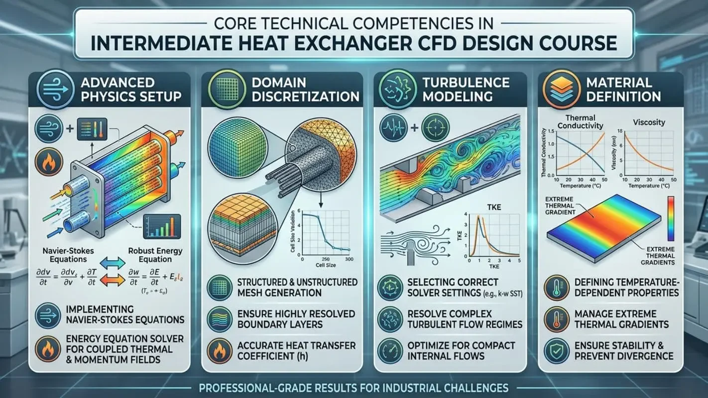
To achieve professional-grade results, simulation engineers must understand both the physical phenomena and the underlying mathematics. Through this targeted intermediate CFD training, you will develop strict core competencies essential for solving complex industrial challenges:
Advanced Physics Setup: Implementing the Navier-Stokes equations effectively alongside a robust energy equation solver to map coupled thermal and momentum fields.
Domain Discretization: Executing structured and unstructured mesh generation for thermal systems, ensuring highly resolved boundary layers that accurately capture the heat transfer coefficient.
Turbulence Modeling: Selecting the correct solver settings to accurately resolve complex turbulent flow regimes inherent in compact internal flows.
Material Definition: Defining temperature-dependent material properties to ensure the simulation accurately responds to extreme thermal gradients without diverging.
Comprehensive Heat Exchanger CFD Simulation Course Modules
This curriculum consists of specialized, production-grade projects that break down the technical complexities of modern heat exchange technology.
Analyzing Multi-Stream Dynamics in Triple Heat Exchanger Simulation
Multi-channel systems present unique challenges regarding fluid mixing and energy exchange. In this module, you will learn to model the complex thermal interactions and internal flow distribution between three disparate fluid streams. By calculating precise temperature gradients, you will evaluate the overall heat transfer effectiveness and ensure uniform thermal loading across the entire system.
Plate Heat Exchanger CFD Design and Performance Evaluation
Compact designs rely on highly corrugated surfaces to induce turbulence. Through focused plate heat exchanger CFD design, you will investigate the direct effects of plate geometry and chevron angles on fluid behavior. You will accurately quantify thermal enhancement mechanisms while strictly predicting pressure drop in heat exchangers to avoid exceeding pumping power limits.
CFD Simulation of Shell and Tube Heat Exchanger Variations
As the backbone of the petrochemical and power industries, shell-and-tube systems require meticulous design. This module delivers an in-depth CFD simulation of shell and tube heat exchanger performance. You will analyze varying baffle configurations, mitigate shell-side flow stagnation, and implement structural modifications to drastically improve overall thermal-hydraulic performance.
Phase Change Material Heat Exchanger Simulation for Energy Storage
Thermal energy storage is a critical frontier in modern engineering. By conducting phase change material heat exchanger simulation, you will utilize advanced multiphase and melting/solidification models. This enables the precise tracking of transient latent heat storage capabilities, evaluating how specific PCMs absorb and release energy over cyclical operational periods.
Next-Generation Nanofluid Heat Transfer CFD
The introduction of nanoparticles into base fluids can dramatically augment thermal conductivity. During the nanofluid heat transfer CFD module, you will explore advanced mixture modeling approaches. You will learn to properly define nanofluid rheology and thermal properties to accurately predict the performance gains these specialized fluids provide in compact heat exchangers.
High-Fidelity Conjugate Heat Transfer Simulation
Fluid-only models often fail to capture true thermal resistance. By executing a strict conjugate heat transfer simulation, you will accurately model the simultaneous solid-fluid interactions. Understanding conjugate heat transfer (CHT) is essential for obtaining realistic temperature fields, mapping conduction through complex fin geometries, and predicting accurate solid domain thermal stress points.
Advanced Solar Thermal Heat Exchanger Modeling
Renewable energy systems operate under variable boundary conditions and complex radiation dynamics. In the solar thermal heat exchanger modeling section, you will integrate radiation models with multiphase flow dynamics. You will assess the impact of concentrated solar flux and fluctuating environmental conditions on the thermal efficiency of the working fluid.
Helical Fin Heat Exchanger Optimization and Geometry Analysis
Finned tube heat exchangers are ubiquitous in HVAC and air-cooled systems. Here, you will compare various helical fin geometries to identify designs that maximize the active heat transfer surface area. The primary objective is to balance the thermal gains against the induced aerodynamic pressure penalty, finding the optimal geometric ratio for peak efficiency.
Evaluating Comparative Solver Methodologies for Thermal Systems
Not all fluid problems require the same numerical approach. You will compare alternative CFD solver methodologies—from steady-state approximations to fully transient, large eddy simulations (LES). Understanding the computational cost versus accuracy trade-offs empowers you to select the most efficient simulation workflow for a given industrial ANSYS Fluent heat exchanger project.
Professional Skills Acquired in Thermal Performance Analysis Course
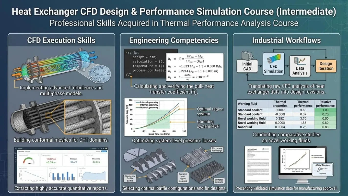
Transitioning from basic simulations to professional-grade thermal performance analysis requires a structured skill set. Below is a breakdown of the specific capabilities you will master:
CFD Execution Skills | Engineering Competencies | Industrial Workflows |
Implementing advanced turbulence and multi-phase models. | Calculating and verifying the bulk heat transfer coefficient. | Translating raw CFD analysis of heat exchanger data into design revisions. |
Building conformal meshes for CHT domains. | Optimizing system-level pressure losses. | Conducting comparative studies on novel working fluids. |
Extracting highly accurate quantitative reports. | Selecting optimal baffle configurations and fin designs. | Presenting validated simulation data for manufacturing approval. |
Real-World Industrial Applications for Heat Exchanger CFD Training course (in ANSYS Fluent)
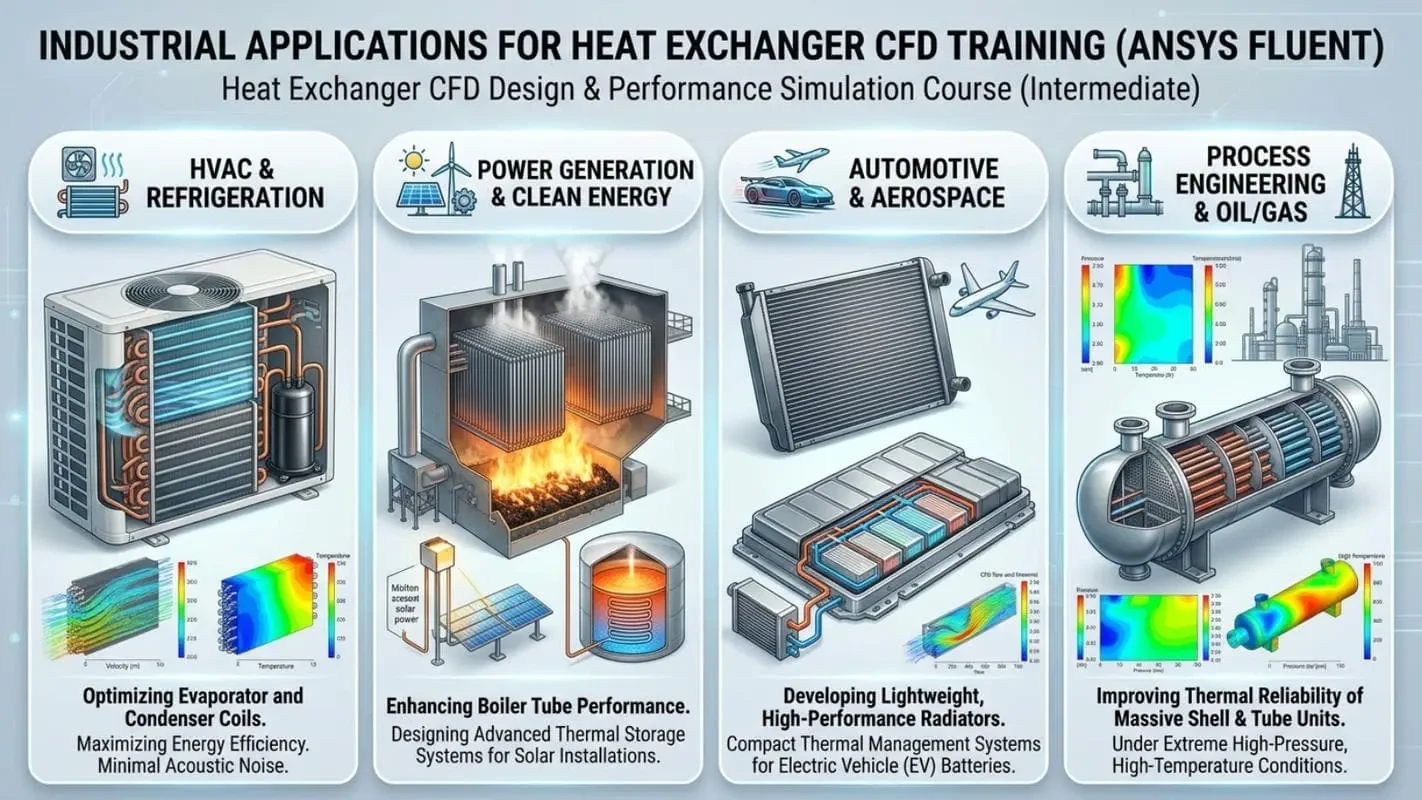
The capability to execute a precise heat exchanger CFD simulation translates directly into high-demand engineering sectors:
HVAC & Refrigeration: Optimizing evaporator and condenser coils for maximum energy efficiency and minimal acoustic noise.
Power Generation & Clean Energy: Enhancing boiler tube performance and designing advanced thermal storage systems for solar installations.
Automotive & Aerospace: Developing lightweight, high-performance radiators and compact thermal management systems for electric vehicle (EV) batteries.
Process Engineering & Oil/Gas: Improving the thermal reliability of massive shell and tube units under extreme high-pressure, high-temperature conditions.
Who Should Master This Heat Exchanger CFD Course?
This intensive program is engineered for professionals and academics who demand precision in thermal systems:
Mechanical & Thermal Engineers: Seeking to validate system performance prior to manufacturing.
HVAC & Energy System Engineers: Aiming to optimize industrial heating and cooling cycles.
CFD Analysts & Simulation Specialists: Looking to expand their portfolio with complex multiphysics and multi-phase heat exchanger modeling.
Graduate Students & Researchers: Requiring validated, high-fidelity numerical methodologies for advanced academic publications.
Why Choose MR CFD for Your Simulation Education?
We don't just teach software functionality; we engineer solutions. If your organization requires dedicated project support, our ANSYS Fluent Consulting division provides industry-leading optimization services. We bring this exact same rigorous, production-level methodology into our educational curriculum. Every project in this course is based on realistic industrial parameters, ensuring the skills you learn are immediately applicable in the professional engineering sector.
Educational Progression and Technical Advancement
Continuous learning is the foundation of engineering excellence. If you need to reinforce your foundational knowledge before tackling this curriculum, we highly recommend starting with our Ansys fluent beginner course.
Once you successfully complete this Ansys fluent intermediate course and master intermediate thermal dynamics, you will be prepared to transition into our Ansys Fluent Advanced Course. For engineers looking to drastically reduce calculation times on dense thermal meshes, exploring ANSYS HPC (High-Performance Computing) integration is the logical next step. Furthermore, if you are looking to build a professional career in simulation, consider applying for a specialized CFD Internship to gain direct, hands-on industry experience.
Secure Your Enrollment and Master Thermal Simulation Today
Stop relying on outdated analytical methods and empirical guesswork. It is time to make data-driven, highly optimized engineering decisions. Enroll in the Heat Exchanger CFD course today, master the governing equations of thermal dynamics, and become the technical authority in industrial fluid simulation.
No. This is an intermediate-level program designed for learners who already understand fundamental CFD concepts and basic simulation workflows.
The course includes shell and tube, plate, finned, solar, PCM-based, nanofluid, and multi-stream heat exchanger applications.
Yes. Several projects focus on performance optimization through geometry modifications, fin design studies, and flow configuration analysis.
Yes. Dedicated projects explore phase change materials (PCM) and latent heat storage applications.
Yes. You will learn how nanofluids can be modeled and evaluated for enhanced thermal performance.
Key parameters include:
Heat transfer rate
Thermal effectiveness
Pressure drop
Temperature distribution
Flow uniformity
Thermal efficiency
Absolutely. Many concepts directly apply to HVAC equipment, thermal management systems, and energy-efficient heat exchanger design.
Yes. The course focuses on practical engineering workflows commonly used in industrial thermal design and performance evaluation.
Yes. Solar heat exchanger simulations and energy storage systems are covered within the project portfolio.
Unlike generic CFD courses, this program focuses entirely on heat exchanger design, thermal analysis, performance evaluation, and engineering optimization, making it highly specialized for thermal engineers.