

Helical Heat Exchanger CFD Simulation, ANSYS Fluent Training
Price: $8
This project investigates the heat transfer inside a helical heat exchanger.
Helical Heat Exchanger CFD Simulation, ANSYS Fluent Training
Price: $8
This project investigates the heat transfer inside a helical heat exchanger.
Introduction
A heat exchanger is a system used to transfer heat between two or more fluids. Heat exchangers are used in both cooling and heating processes. The fluids may be separated by a solid wall to prevent mixing, or they may be in direct contact. They are widely used in space heating, refrigeration, air conditioning, power stations, chemical plants, petrochemical plants, petroleum refineries, natural-gas processing, and sewage treatment. The classic example of a heat exchanger is found in an internal combustion engine in which a circulating fluid known as engine coolant flows through radiator coils, and air flows past the coils, which cools the coolant and heats the incoming air. Another example is the heat sink, which is a passive heat exchanger that transfers the heat generated by an electronic or mechanical device to a fluid medium, often air or a liquid coolant.
Helical Heat Exchanger Project description
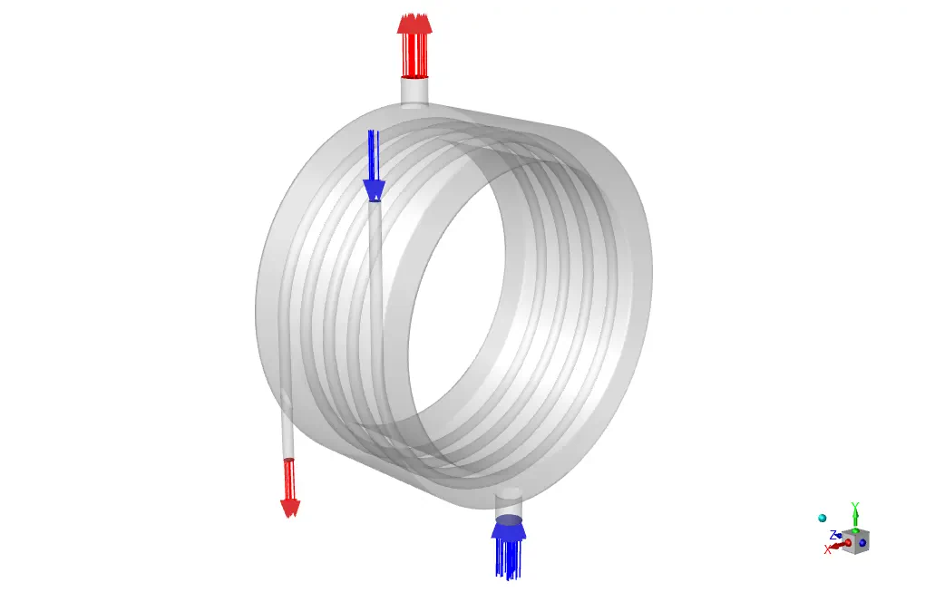
In this project, the heat transfer inside a helical heat exchanger is investigated by ANSYS Fluent software. The helical heat exchanger consists of a number of coils (helical tubes) with a helix curve (similar to a spring) that are embedded in a shell. To increase the heat transfer level, several pipes are placed in a spiral format next to each other, and all are connected to one inlet and outlet. Numerous experimental studies have been performed on helical tubes' flow and heat transfer characteristics. The energy equation is activated to obtain temperature distribution inside the computational domain. The standard k-epsilon model is exploited to solve turbulent flow equations. It should be noted that the ideal gas model has been used to determine the density changes in proportion to temperature.
Helical Heat Exchanger Geometry & Mesh
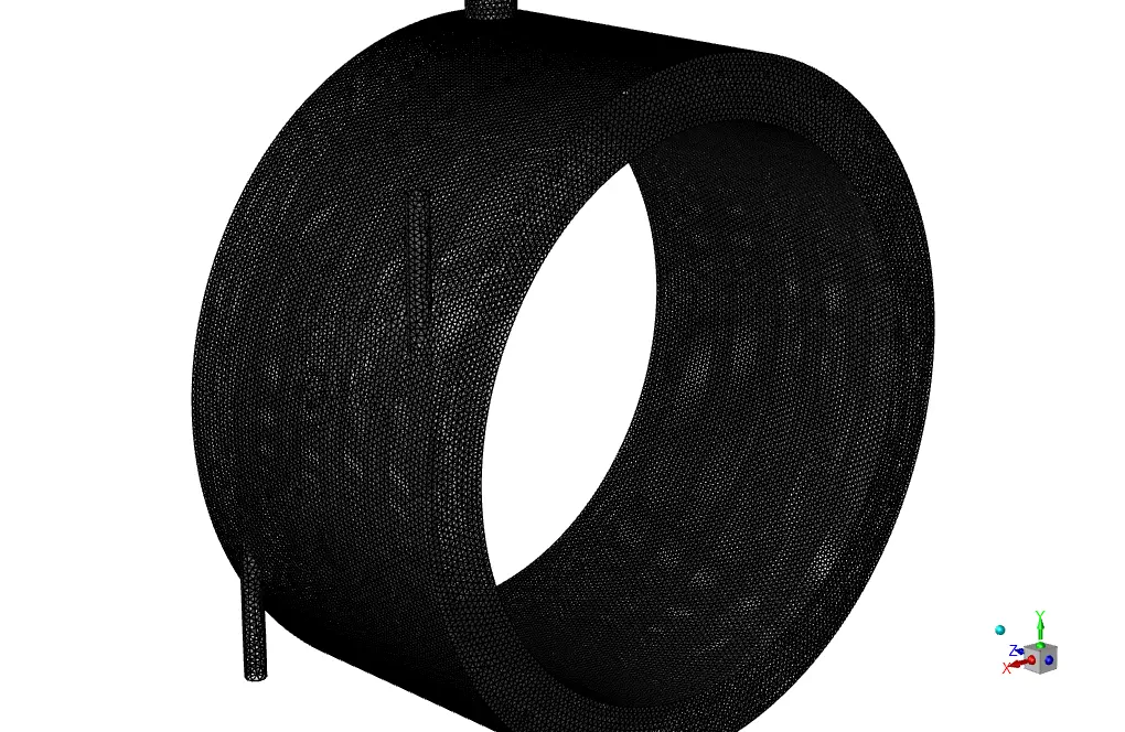
The geometry of this project is designed in CATIA and meshed in GAMBIT. The mesh type used for this geometry is unstructured, and the element number is 890710.
CFD simulation settings
The critical assumptions considered in this project are:
- The simulation uses a pressure-based solver.
- The present simulation's results are steady and do not change as a function of time.
- We ignore the effect of gravity.
The applied settings are summarized in the following table.
| Models | ||
| Viscous model | k-epsilon | |
| k-epsilon model | standard | |
| near wall treatment | standard wall function | |
| Energy | on | |
| Boundary conditions | ||
| Inlet | Velocity inlet | |
| Inlet2 | 5 m/s | |
| Temperature | 340 K | |
| Inlet-2 | 5m/s | |
| Temperature | 300 K | |
| Outlet | Pressure outlet | |
| Gauge pressure | 0 Pa | |
| Walls | Stationary wall | |
| wall | Heat flux | 0 W/m2 |
| wall.5 | Thermal condition | coupled |
| Solution Methods | ||
| Pressure-velocity coupling | coupled | |
| Spatial discretization | Pressure | PRESTO! |
| Momentum | first-order upwind | |
| Energy | first-order upwind | |
| turbulent kinetic energy | first-order upwind | |
| turbulent dissipation rate | first-order upwind | |
| Initialization | ||
| Initialization method | Standard | |
| gauge pressure | 0 Pa | |
| Velocity (x,y,z) | (0,0,0) m/s | |
| temperature | 334.3642K | |
| Turbulent kinetic energy | 0.09375 m2/s2 | |
| Turbulent dissipation rate | 78.72302 m2/s3 | |
Results
We obtain and present the contours of velocity, temperature, etc., in 3D and 2D.