

Heller Indirect Dry Cooling Tower Transient Simulation
Price: $10
In this project, the transient simulation of the Heller cooling tower is investigated.
Heller Indirect Dry Cooling Tower Transient Simulation
Price: $10
In this project, the transient simulation of the Heller cooling tower is investigated.
Heller Indirect Dry Cooling Tower Transient Simulation, ANSYS Fluent Training
In this project, the transient simulation of the Heller cooling tower is investigated by ANSYS Fluent software. Heller cooling tower is an indirect heat exchanging mechanism in which airflow over the water stream and heat exchange process density decreases, and an upward flow is generated. In the present work, an ideal gas model is used for air density modeling. The ideal gas density model is based on the relationship between density and local fluid temperature. Higher the temperature, the lower the density, and the higher the upward force on fluid volume due to buoyancy effects.
Heller Geometry and mesh
The fluid domain's geometry is designed in Design Modeler, and the computational grid is generated using Ansys Meshing. The mesh type is unstructured, and the element number is 230000.
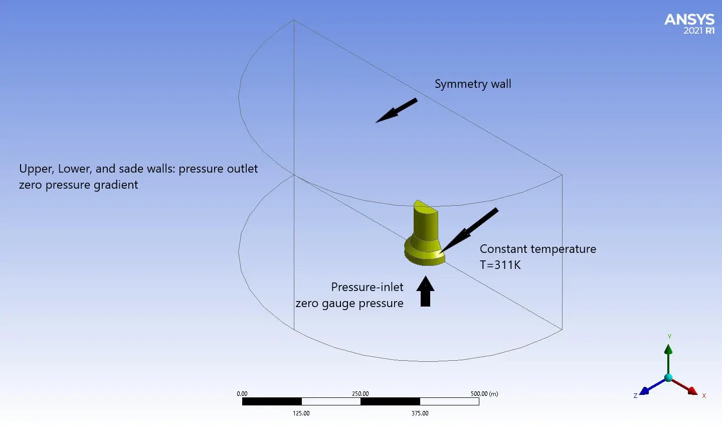
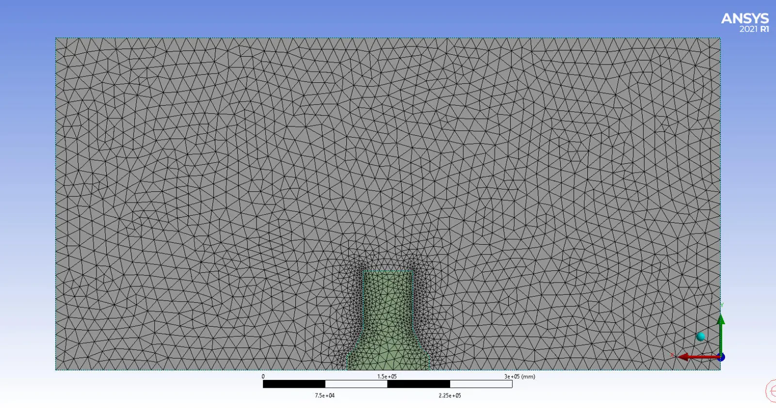
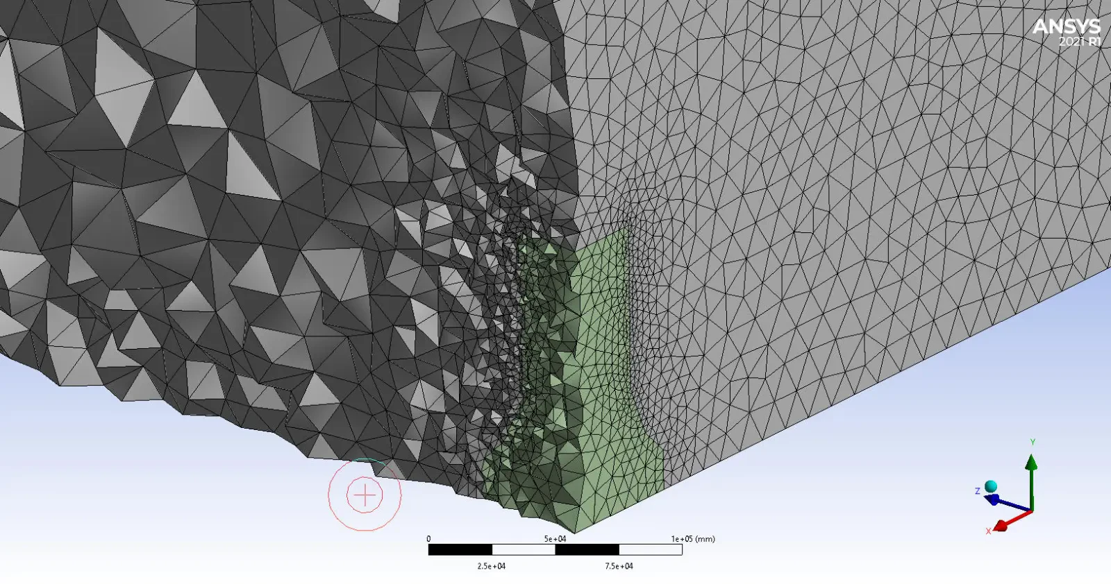
Heller CFD Simulation
Critical assumptions:
- The solver type is assumed density Based.
- Time formulation is assumed unsteady.
- Gravity effects are considered in the Y direction equal to –9.81 m/s2.
The following table represents a summary of the defining steps of the problem and its solution.
| Models (Heller) | ||
| Viscous | K-epsilon | Standard |
| Near wall treatment | Standard wall treatment | |
| Energy | on | |
| Materials (Heller) | ||
| Fluid | Definition method | FLUENT database |
| Material name | air | |
| Density model | Ideal gas | |
| Boundary conditions | ||
| Inlet | Type | Pressure inlet |
| Gauge pressure | 0 kPa | |
| Thermal | 288.61 K | |
| Radiator | Type | Wall |
| Thermal | 311.2 K | |
| Wall thickness | 1 m | |
| Heat generation rate | 51352 W/m3 | |
| Solver configurations (Heller) | ||
| Formulation | Implicit | |
| Flux type | Roe-FDS | |
| Spatial discretization | Gradient | Least square cell-based |
| Momentum | Second-order Upwind | |
| K | First-order Upwind | |
| Epsilon | First-order Upwind | |
| Run calculation | Time step size | Adaptive |
| Total time | 1000 s | |
| No. of fixed time steps | 2 | |
| Initial time step size | 10e-5 | |
| Max items per time step | 20 | |
Results and discussion
The pressure difference in orders of 10kPa is generated inside the cooling tower. The velocity of air, only under the influence of buoyancy force, reaches 90 m/s inside the cooling tower and reaches a maximum of 170 m/s on the edge of the cooling tower exit.