

Vortex Separator, Hydrodynamic Eulerian CFD Simulation, ANSYS Fluent Training
Price: $80
The present problem simulates two-phase flow inside a hydrodynamic vortex separator using ANSYS Fluent software.
Vortex Separator, Hydrodynamic Eulerian CFD Simulation, ANSYS Fluent Training
Price: $80
The present problem simulates two-phase flow inside a hydrodynamic vortex separator using ANSYS Fluent software.
Hydrodynamic Vortex Separator Project Description
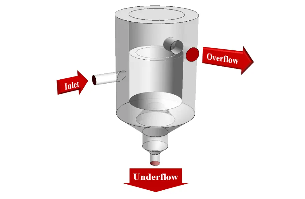
The present problem simulates two-phase flow inside a hydrodynamic vortex separator using ANSYS Fluent software. These hydrodynamic vortex separators (HDVS), can separate soluble particles in a fluid from the base fluid. The structure of these devices is such that the flow of the solution entering the system is significantly rotated. This high rotation of the flow causes the fluid movement path inside the system to be significantly longer. This lengthening of the solvent flow path provides an opportunity to separate the suspended particles in the fluid and settle them in the system. Therefore, the Eulerian multiphase model has been used.
The Eulerian multiphase model is considered the most complex model for defining multiphase flows because it solves a set of momentum and conservation equations for each phase independently. From the Eulerian model in applications such as bubble columns, droplet flows, particle-laden flows with a volume fraction of more than 10%, pneumatic transitions for granular, liquid flows, Fluidized beds are used for solid-gas flows, the slurry flows, particle suspension, and sedimentation phenomena as solid-liquid flows. In the present simulation, water flow is defined as a base fluid with a density of 1000 kg.m-3 and a viscosity of 0.001 kg.m-1.s-.
Hydrodynamic Vortex Separator Project Description
The secondary phase in the form of particles with a density of 1060 kg.m-3 and a viscosity of 0.0046 kg.m-1.s-1 is defined. The particle dispersion in the base liquid is defined as granular, and the particle diameter is defined as 0.000006 m. The flow of water and its soluble particles enter the device at a rate of 0.36 m.s-1 through an intermediate duct; While the volume fraction of water flow is equal to 0.4 and the volume fraction of soluble particles is equal to 0.6. Finally, after the separation process, this solution leaves the outlet ducts at the top of the device (for water passage) and the bottom of the device (for particle settling).
Hydrodynamic Vortex Separator Geometry & Mesh
The present model is designed in three dimensions using Design Modeler software. The current model is related to a vertical hydrodynamic vortex separator. The cylindrical part of this vertical device's body is 0.3 m in diameter and 0.63 m high. In this model, a pipe for inlet current is located on the middle part of the body, and two outlet pipes are located in the lower part of the model and on the upper part of the model body.
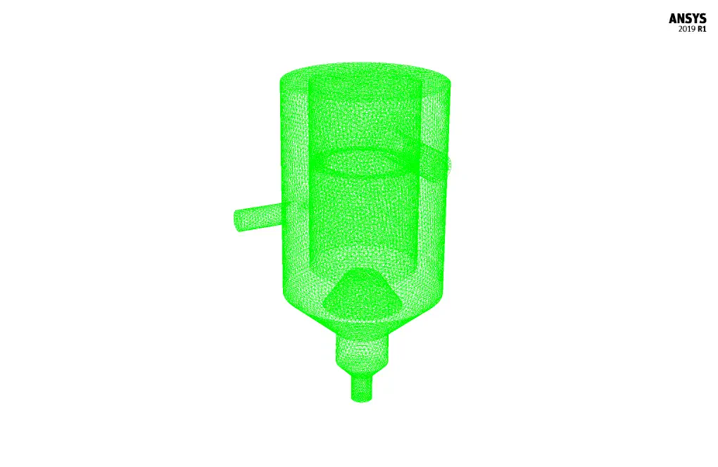
We carry out the meshing of the model using ANSYS Meshing software, and the mesh type is unstructured. The element number is 472707. The following figure shows the mesh.
CFD Simulation
We consider several assumptions to simulate the present model:
- We perform a pressure-based solver.
- The simulation is unsteady (Transient Solver).
- The gravity effect on the fluid is equal to -9.81 m.s-2 along the Z-axis.
The following table represents a summary of the defining steps of the problem and its solution:
| Models (Hydrodynamic Vortex Separator) | ||
| Viscous | Reynolds Stress | |
| Reynolds stress model (RSM) | linear pressure-strain | |
| near-wall treatment | standard wall function | |
| Multiphase Model | Eulerian | |
| number of eulerian phases | 2 | |
| formulation | implicit | |
| Boundary conditions (Hydrodynamic Vortex Separator) | ||
| Inlet | Velocity Inlet | |
| gauge pressure | 0 pascal | |
| velocity magnitude for the primary phase | 0.36 m.s-1 | |
| velocity magnitude for the secondary phase | 0.36 m.s-1 | |
| volume fraction for particle | 0.6 | |
| Overflow | Pressure Outlet | |
| gauge pressure | 0 pascal | |
| Underflow | Pressure Outlet | |
| gauge pressure | 0 pascal | |
| Walls | Wall | |
| wall motion | stationary wall | |
| Methods (Hydrodynamic Vortex Separator) | ||
| Pressure-Velocity Coupling | Phase Coupled SIMPLE | |
| Pressure | PRESTO | |
| momentum | second order upwind | |
| volume fraction | first order upwind | |
| turbulent kinetic energy | second order upwind | |
| turbulent dissipation rate | second order upwind | |
| Reynolds stresses | first order upwind | |
| Initialization (Hydrodynamic Vortex Separator) | ||
| Initialization methods | Hybrid | |
Results
At the end of the solution process, two-dimensional and three-dimensional contours related to the mixture pressure, base fluid velocity, soluble particle velocity, and the volume fraction of the base fluid and soluble particles are obtained. As can be seen from the pictures, it can be said that the flow of water is directed to the upper outlet of the device, and the flow of settled particles is directed to the lower outlet of the device. This shows that the system's performance is good and exhibits its primary task of separating soluble particles from the base fluid.