Intake of Jet Engine CFD Simulation, ANSYS Fluent Tutorial
Price: $12
- The problem numerically simulates airflow in Jet Intake using ANSYS Fluent software.
- We design the 3-D model by the Design Modeler software.
- We Mesh the model by ANSYS Meshing software, and the element number equals 389136.
Intake of Jet Engine CFD Simulation, ANSYS Fluent Tutorial
Price: $12
- The problem numerically simulates airflow in Jet Intake using ANSYS Fluent software.
- We design the 3-D model by the Design Modeler software.
- We Mesh the model by ANSYS Meshing software, and the element number equals 389136.
Description
The present problem simulates the airflow in a three-dimensional Jet Intake using ANSYS Fluent software. We perform this CFD project and investigate it by CFD analysis.
The present model is designed in three dimensions using Design Modeler software. The model’s geometry includes a cylindrical computational domain where the jet intake is placed.
The meshing of this present model has been generated by Ansys Meshing software. The total cell number is 389136.
Intake Methodology
In this project, ANSYS Fluent software investigates steady airflow in a three-dimensional jet intake. Jet engines are one of the aerodynamic primaries and most commonly used thrusters. Jet engines, including the intake section similar to the present work, are used for subsonic and supersonic flows.
In subsonic flows, the flow velocity is higher than free stream velocity inside the intake domain, while in supersonic flows, the flow Mach number increases inside the intake domain. Intake is the first section through which incoming air flows to the engine.
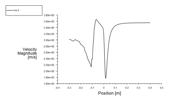
Intake geometry decreases and increases the cross-section to make the airflow uniform. In this project, air flows into the domain with a velocity of 3.55 m/s. Moreover, the standard k-epsilon model is used to solve turbulent fluid equations.
Intake Conclusion
At the end of the solution process, two- and three-dimensional contours related to pressure, velocity, streamlines, and velocity vectors are obtained. Furthermore, based on the data calculated using the Fluent software, the air mass flow rate in the intake domain is equal to 0.02525548 kg/s.
Due to a sudden decrease in the cross-section of fluid flow, velocity inside the intake reaches higher magnitudes equal to 3.6 m/s. Before entering the intake domain, airflow pressure reaches higher values equal to 5.96 Pa due to the sudden decrease in flow cross-section.