

Inviscid Flow Around The Wing, CFD Simulation Training
Price: $10
In this project, Inviscid Fluid Flow Over the Wing has been simulated, and the simulation results have been investigated.
Inviscid Flow Around The Wing, CFD Simulation Training
Price: $10
In this project, Inviscid Fluid Flow Over the Wing has been simulated, and the simulation results have been investigated.
Inviscid Flow Around The Wing, CFD Simulation ANSYS Fluent Training
A wing is a fin that produces lift while moving through air or other fluid. Accordingly, wings have streamlined cross-sections subject to aerodynamic forces and act as airfoils. A wing's aerodynamic efficiency is expressed as its lift-to-drag ratio.
The design and analysis of aircraft wings are one of the principal applications of the science of aerodynamics, which is a branch of fluid mechanics. In principle, the airflow properties around any moving object can be found by solving the Navier-Stokes equations of fluid dynamics. However, these equations are notoriously difficult to solve except for simple geometries, and simpler equations are used. For a wing to produce lift, it must be oriented at a suitable angle of attack. When this occurs, the wing deflects the airflow downwards as it passes the wing. Since the wing exerts a force on the air to change its direction, it must also exert an equal and opposite force on the wing.
Inviscid fluid flow Description
In this project, we simulate a wing with ANSYS Fluent software. In addition to this, this project aims to stimulate the inviscid flow around the wing and obtain the pressure and velocity around it.
Geometry and mesh
The geometry of the solution consisted of Geometric defining parameters, including chord line, angle of attack, leading edge, and trailing edge. The 3D geometry of this project has been produced with ANSYS Design Modeler software:
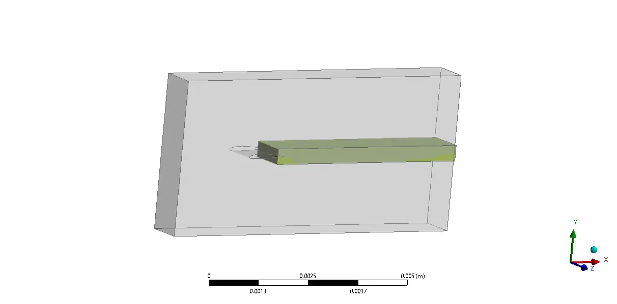
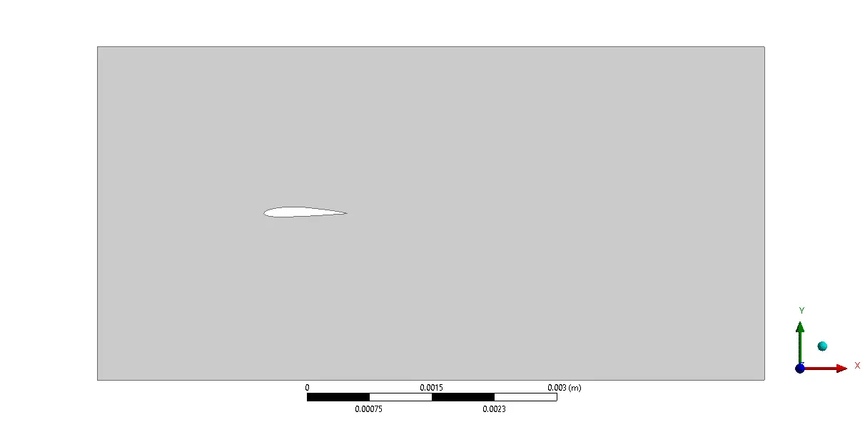
Mesh is created with ANSYS Meshing software, and the mesh type is unstructured. The number of cells is 5558992.
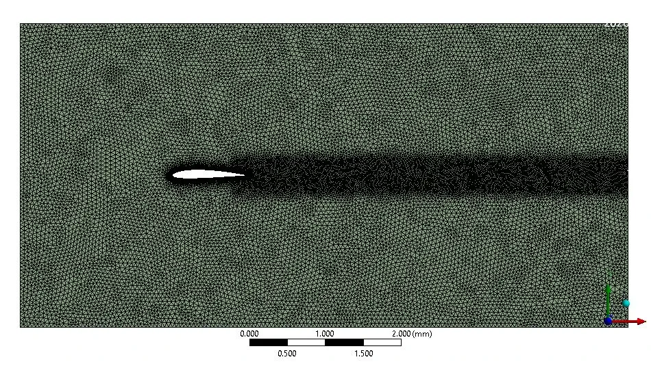
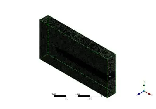
We consider several assumptions to simulate the present model:
- We perform a pressure-based solver.
- The simulation is steady.
- The gravity effect on the fluid is ignored.
The following table represents a summary of the defining steps of the problem and its solution:
| Models | ||
viscous | inviscid | |
| Boundary conditions | ||
airfoil | wall | |
inlet | Velocity inlet | |
velocity | 30 m/s | |
outlet | Pressure outlet | |
gauge pressure | 0 Pascal | |
Sym1 | symmetry | |
Sym2 | Symmetry | |
| Solution Methods | ||
Pressure-velocity coupling | Coupled | |
Spatial discretization | pressure | second-order |
momentum | second-order upwind | |
Initialization | ||
Initialization method | Standard | |
Run calculation | ||
Number of time step | 120 | |
Results
In this simulation, three-dimensional contours are related to pressure, velocity, etc., are presented. Pressure and velocity results The results section shows that, as expected, the maximum velocity was found at the top level of the airfoil, while the maximum pressure was at the front edge, where the speed was at the minimum and occurred at the stagnation point. A stagnation point in the flow, where the velocity of a fluid is zero. Stagnation points exist at the surface of objects in the flow field, where the flow is brought to rest by the thing.