

Manifold of Engine CFD Simulation by Species Transport
Price: $16
In this project, steady air flow mixing with fuel is investigated in an engine manifold with 3 outlets, where only one outlet is open and the other 2 outlets are blocked.
Manifold of Engine CFD Simulation by Species Transport
Price: $16
In this project, steady air flow mixing with fuel is investigated in an engine manifold with 3 outlets, where only one outlet is open and the other 2 outlets are blocked.
Manifold of Engine CFD Simulation by Species Transport, ANSYS Fluent
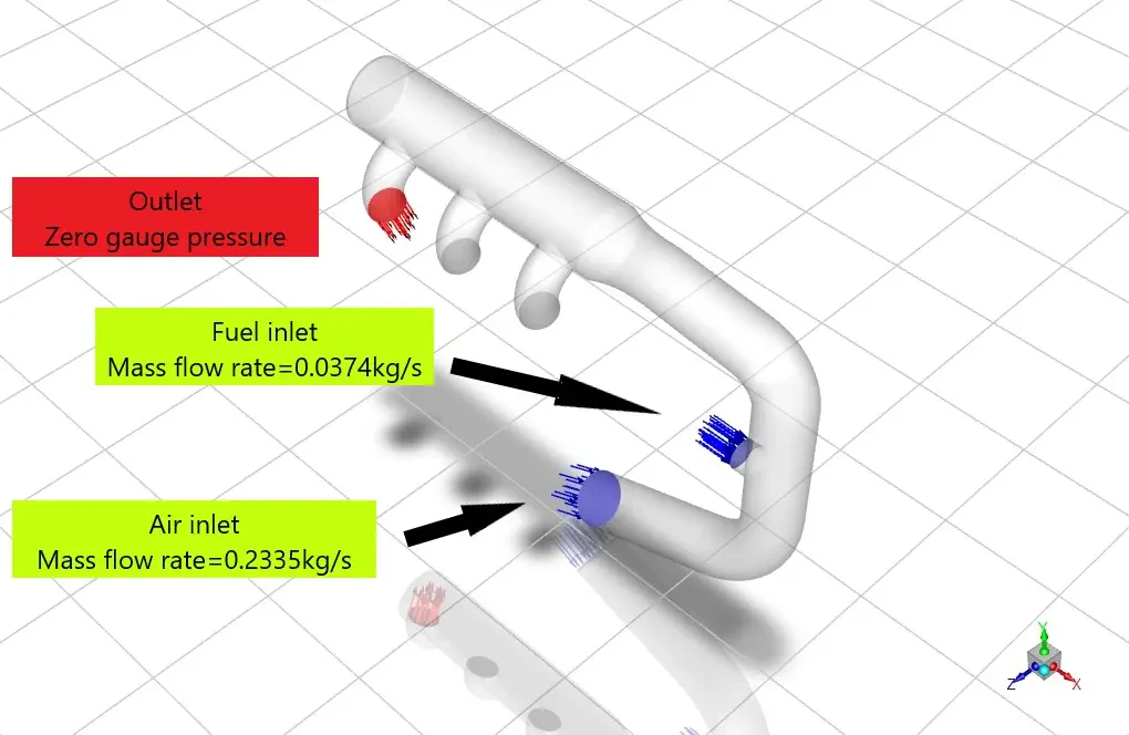
In this project, steady air flow mixing with fuel is investigated by ANSYS Fluent in a 3-outlet manifold where only one outlet is adequate, and the other 2 outlets are blocked. Two inlets provide air and fuel flow into the domain. Air and fuel flow rates are equal to 0.2335 and 0.0374 kg/s. Species entering the domain via air inlet are nitrogen and oxygen with mass fractions equal to 0.79 and 0.21, respectively. Species entering the domain via fuel inlet are CO, CH4, CO2, N2, and H2, with mass fractions equal to 0.06, 0.004, 0.1, 0.081, and 0.03, respectively.
Engine Manifold Geometry and mesh
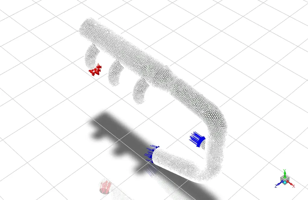
The geometry of the fluid domain is designed in the Design Modeler, and the computational grid is generated using ANSYS Meshing. The mesh type is unstructured, and the element number is 231646.
Solver configuration
Critical assumptions:
- The solver type is assumed Pressure Based.
- Time formulation is assumed to be Steady.
- Gravity effects are neglected.
The following table summarizes the defining steps of the problem and its solution.
| Models (Engine Manifold) | ||
| Energy | On | |
| Viscous | K-epsilon model | Standard |
| Near wall treatment | Enhanced wall treatment | |
| Species transport | Model | Species transport |
| Options | Inlet diffusion (on) | |
| The diffusion energy source (on) | ||
| Mixture properties | Mixture-template | |
| Materials (Engine Manifold) | ||
| Fluid | Definition method | Fluent Database |
| Material name | CO2 | |
| Material name | CO | |
| Material name | H2 | |
| Material name | CH4 | |
| Material name | N2 | |
| Material name | O2 | |
| Material name | H2O | |
| Boundary conditions (Engine Manifold) | ||
| Inlet_air | Type | Mass flow inlet |
| Mass flow rate | 0.2335 kg/s | |
| Turbulent intensity | 4% | |
| Hydraulic diameter | 0.05 m | |
| Species | N2 (0.79) | |
| O2 (0.21) | ||
| Inlet fuel | Type | Mass flow inlet |
| Mass flow rate | 0. 0374 kg/s | |
| Turbulent intensity | 5% | |
| Hydraulic diameter | 1 m | |
| Species | N2 (0.801) | |
| CO (0.06) | ||
| CH4 (0.004) | ||
| CO2 (0.1) | ||
| H2 (0.03) | ||
| Solver configurations (Engine Manifold) | ||
| Pressure-velocity coupling | Scheme | PISO |
| Spatial discretization | Gradient | Least square cell-based |
| Pressure | Standard | |
| Momentum | Second order Upwind | |
| K | First order Upwind | |
| Epsilon | First order Upwind | |
Results and discussion
The mixture mass flow rate at the outlet is equal to 0.2709012 kg/s. Although 2 outlets are considered walls and are blocked, mixture pressure on these surfaces is critical. Pressure on outlets 1 and 2 equals 771.44639 and 780.98142 Pa, respectively.