Manometer of Venturimeter CFD Simulation by Ansys Fluent
Price: $80
In this project, a monometer has been simulated, and the results of this simulation have been investigated.
Manometer of Venturimeter CFD Simulation by Ansys Fluent
Price: $80
In this project, a monometer has been simulated, and the results of this simulation have been investigated.
Description
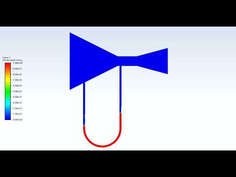
In this project, we study a Manometer of Venturimeter CFD Simulation by Ansys Fluent, and it has been shown how there is variation in U-tube manometric fluid column. The multiphase VOF model has been used. A convergent and divergent nozzle has been used to create a pressure difference. One end of the manometer is attached at the throat, and the other at the converging section. There is a rise in the liquid column in the U- tube manometer at the low-pressure region.
Monometer of Venturimeter CFD Simulation by Ansys Fluent
Venturimeters are pressure measurement devices that are commonly used in everyday life. For example, pressures in piping systems are constantly monitored using these devices. The U-tube manometer is a special manometer that gets its name from its U-shaped tube. The straight portions of this U are commonly referred to as the manometer's arms, limbs, or ends. The manometer is typically filled with a dense, colored fluid called the manometer fluid, which is used to visualize the pressure difference between the two ends of the tube. As the pressure at one of its ends increases, the manometer fluid inside the tube is pushed downward at that end.
This causes the manometer fluid to rise at the other end of the device. The difference in the fluid levels between the two ends is then used to measure the pressure difference. When used properly, the manometer, one of the earliest pressure-measuring instruments, is very accurate. The manometer has no moving parts subject to wear, age, or fatigue. Manometers operate on the Hydrostatic Balance Principle: a liquid column of known height will exert a known pressure when the weight per unit volume of the liquid is known.
Geometry & Mesh
The 2-D geometry of the present model is generated using Design Modeler software.

The meshing of the present model has been done using Ansys Meshing software. The mesh type is unstructured in all of the computational domains, and the element number is equal to 42,413.

CFD Simulation
To simulate the present model, we consider several assumptions:
- The solver is pressure-based.
- The current simulation is unsteady in terms of time.
- The gravity effect is equivalent to -9.81 m.s-1.
Here is a summary of the steps for defining the problem and its solution in the following table:
| Models | |||
Multiphase | |||
| Homogeneous model | Volume of fluid | ||
| Number of Eulerian phases | 2(air& mercury) | ||
| Interface modeling | Sharp | ||
| Formulation | explicit | ||
| Body force formulation | Implicit body force | ||
Viscous model | k-epsilon | ||
Material Properties | |||
Air | |||
| Density | 1.225 | ||
| viscosity | 1.7894e-05 | ||
mercury | |||
| Density | 13529 | ||
| viscosity | 0.001523 | ||
| Boundary conditions | |||
| Inlet air | Velocity inlet | ||
| volume fraction | 1 | ||
| velocity magnitude | 1.8 m.s-1 | ||
| Outlet | Pressure outlet | ||
gauge pressure | 0 Pascal | ||
air backflow volume fraction | 0 | ||
| Solution Method | |||
Pressure-velocity coupling | Piso | ||
Spatial discretization | pressure | presto | |
momentum | first-order upwind | ||
Volume fraction | Geo reconstruct | ||
Turbulent kinetic energy | First-order upwind | ||
Turbulent dissipation rate | First-order upwind | ||
| Initialization | |||
Initialization method | Standard | ||
Patch | Phase | air | |
Variable | Volume Fraction | ||
Registers to patch | region_0 | ||
Value | 0 | ||
| Run calculation | |||
| Time step size | 0.001 | ||
| Max iterations/time step | 10 | ||
Number of time steps | 1200 | ||
Monometer Results
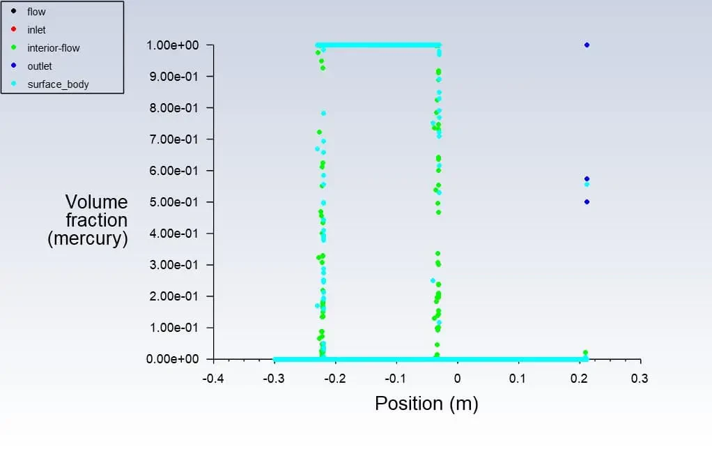
First, a volume fraction diagram was drawn in different positions in this simulation. Then two-dimensional contours related to density, streamline, air volume fraction and mercury volume fraction were obtained. The images show that Initially, the height of the liquid column is equal on both sides. But as the gas enters the manometer, the height of the mercury column changes.