

Open Channel Flow (Two-Phase) CFD Simulation, ANSYS Fluent Training
Price: $28
In this analysis, the two-phase flow of water and air inside an open channel is investigated.
Open Channel Flow (Two-Phase) CFD Simulation, ANSYS Fluent Training
Price: $28
In this analysis, the two-phase flow of water and air inside an open channel is investigated.

Introduction
Open channel is waterway channel, or artificial waterways, for water conveyance, or to service water transport vehicles. They may also help with irrigation. It can be thought of as an artificial version of a river. Nowadays, the use of canals in the industry has received a lot of attention in applications including air ducts and water transmissions. The shape and dimensions of the channels also largely depend on their uses.
Open Channel Flow Project description
In this analysis, the two-phase flow of water and air inside an open channel is investigated by ANSYS Fluent software. The standard k-omega model is used for solving turbulent flow equations. Also, multi phase VOF model with the use of an open channel setting is activated to simulate two phases of water and air inside the channel. The water enters the channel with a mass flow rate of approximately 60Kg/s and its interaction with the air phase inside the channel is simulated.
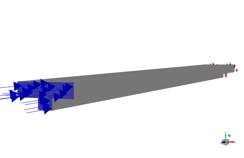
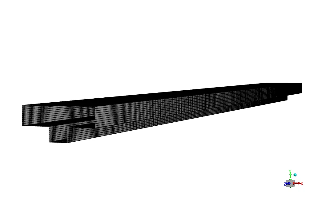
Open Channel Geometry and mesh
The geometry of this project is designed in ANSYS design modeler® and meshed inside ANSYS meshing®. The meshes type used for this geometry is structured and the total number of elements is 214560.
Open Channel Flow CFD Simulation Settings
The key assumptions considered in this project are:
- Simulation is done using pressure-based solver.
- The present simulation and its results are considered to be steady and do not change as a function time.
- The effect of gravity has been taken into account and is equal to -9.81 in Y direction.
The applied settings are recapitulated in the following table.
| Models | ||
| Viscous model | k-omega | |
| k-omega model | standard | |
| k-omega option | Shear flow correction | |
| Multiphase | VOF | |
| VOF sub-model | Open channel | |
| Primary phase | Air | |
| Secondary phase | water | |
| Boundary conditions | ||
| Inlet | Mass flow inlet | |
| Water Mass flow rate | 60.071524 Kg/s | |
| Open channel | ||
| Free surface level | 0.24 m | |
| Bottom level | 0 m | |
| Density interpolation method | From neighboring cell | |
| Outlet | Pressure outlet | |
| Walls | ||
| wall motion | stationary wall | |
| Solution Methods | ||
| Pressure-velocity coupling | SIMPLE | |
| Spatial discretization | pressure | PRESTO! |
| momentum | second order upwind | |
| Volume fraction | compressive | |
| turbulent kinetic energy | first order upwind | |
| turbulent dissipation rate | first order upwind | |
| (open channel) | Initialization | |
| Initialization method | Standard | |
| gauge pressure | 0 Pa | |
| velocity (x,y,z) | 0 m/s-1 | |
| Turbulent kinetic energy | 1 m2/s2 | |
| specific dissipation rate | 1 m2/s3 | |
| Water volume fraction | 0 | |
Results
Different contours of velocity, pressure and water volume fraction are presented in 3D and 2D.