Orifice for Methane Gas Flow, CFD Simulation by ANSYS Fluent Training
Price: Free
- The problem numerically simulates the Orifice for Methane Gas Flow using ANSYS Fluent software.
- We design the 3-D model by the Design Modeler software.
- We mesh the model with ANSYS Meshing software.
- The mesh type is Structured, and the element number equals 54648.

Description
The problem simulates methane gas flow through an Orifice within the canal using ANSYS Fluent software. We perform this CFD project and investigate it by CFD analysis.
The simplest orifice model consists of a perforated plate perpendicular to the desired channel’s fluid flow path. The present model is designed in three dimensions using Design Modeler software.
The model is a channel 12 inches long and 0.5 inches in diameter, in the middle of which a cross-sectional reduction means with a diameter of 0.25 inches exists.
The meshing of the present model has been done using ANSYS Meshing software. The mesh type is Structured, and the element number equals 54648.
Orifice Methodology
The orifice is one of the most common devices for measuring mass flow using pressure difference transmitters.
The orifices’ operating mechanism is such that when the fluid passes through an orifice, its velocity increases due to the reduction of the cross-sectional area of the flow and according to the law of mass conservation and flow constant and according to the Bernoulli principle.
Similarly, when the fluid exits the orifice, the flow velocity decreases again due to the increase in the cross-sectional area of the flow. As a result, the flow pressure increases.
Therefore, a certain amount of pressure difference appears on both sides of the orifice, measured using pressure transmitters and built-in pressure sensors.
As a result, the orifice flow meter uses the same amount of pressure difference to calculate the flow rate of the fluid passing through the desired channel (taking into account the amount of pressure drop and the ratio of the diameter of the orifice hole to the channel diameter).
The fluid studied in this simulation is methane gas, with a density of 0.6679 kg/m3 and a viscosity of 0.00001087 kg/m.s. This flow enters the channel at a velocity equal to 0.033 m/s and exits at a pressure equal to atmospheric pressure.
Also, the RNG k-epsilon model is used to solve turbulent fluid equations.
Orifice Conclusion
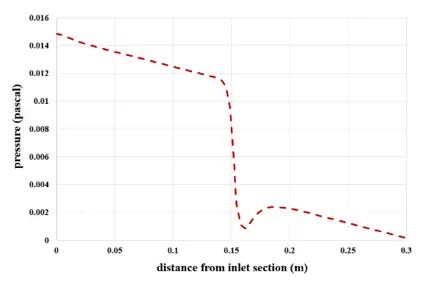
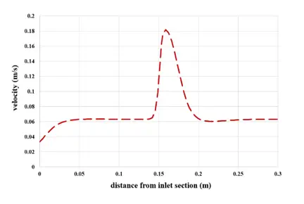
At the end of the solution process, two-dimensional and three-dimensional contours related to velocity and pressure are obtained. Also, the diagram of pressure and velocity changes in the direction of the channel’s central axis and crossing the section related to the orifice has been obtained.
As can be seen from the diagrams and contours, the flow velocity suddenly increases and decreases when the fluid flows through the orifice due to a sudden change in cross-sectional area. The pressure drop in the fluid flow in the path passing through the orifice section can also be seen.