

Paramotor, Ansys Fluent CFD Simulation Training
Price: $10
In this project, a flow in a paramotor has been simulated, and the simulation results have been investigated.
Paramotor, Ansys Fluent CFD Simulation Training
Price: $10
In this project, a flow in a paramotor has been simulated, and the simulation results have been investigated.
Paramotor Project Description
The present simulation is about a paramotor in a paraglider via ANSYS Fluent. A paramotor is the propulsion part of a paraglider that attaches to the pilot's seat. These engines are powered by gasoline and have fan blades attached to them. This simulation defines a cylindrical computational domain for airflow with a temperature of 26.85 C. For inlet and outlet boundaries of this domain, a pressure boundary condition is defined to determine the direction of air movement according to the amount of pressure. In the middle part of this model, a surface is defined as a fan, and the fan boundary condition with 383.8-pascal pressure jump is used. The aluminum casing of the engine with its thermocouple is defined behind the fan; It is assumed that the inner wall inside the engine has a constant temperature equal to 157 C. It is assumed that this temperature is defined based on the heat generated by the combustion inside the engine.
Geometry & Mesh
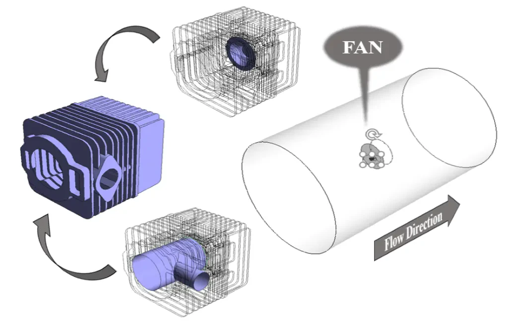
The present model is designed in the 3D model via Design Modeler. This model includes a domain designed with a fan in the middle. The following figure shows the geometry of the model.
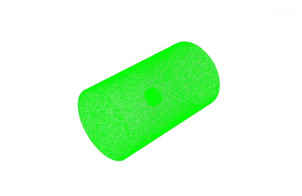
The mesh of the present model has been done via ANSYS Meshing. Mesh is done unstructured, and the number of cells equals 1550207. The following figure shows the mesh of the model.
Paramotor Set-Up & Solution
Assumptions used in this simulation :
- Pressure-based solver is used.
- The present simulation is steady.
- The effect of gravity is ignored.
| Models | ||
| Viscous | k-epsilon | |
| Near-wall | standard | |
| near wall treatment | standard wall function | |
| Energy | On | |
| Boundary conditions | ||
| Inlet | Pressure Inlet | |
| gauge total pressure | 0 pascal | |
| total temperature | 26.85 C | |
| Inner Wall of the Thermocouple | Wall | |
| wall motion | stationary wall | |
| thermal conditions | coupled | |
| Inner Wall | Wall | |
| temperature | 157 C | |
| Outlet | Pressure Outlet | |
| gauge pressure | 0 pascal | |
| Fan | Fan | |
| pressure jump profile | 383.8 pascal | |
| Symmetry Wall | Symmetry | |
| Methods | ||
| Pressure-Velocity Coupling | SIMPLE | |
| pressure | Second-order | |
| momentum | Second-order upwind | |
| turbulent kinetic energy | First-order upwind | |
| turbulent dissipation rate | First-order upwind | |
| energy | Second-order upwind | |
| Initialization | ||
| Initialization methods | standard | |
| gauge pressure | 0 pascal | |
| velocity (x,y,z) | 0 m.s-1 | |
| temperature | 26.85 C | |
Paramotor Results
After the solution, 2D and 3D temperature, velocity, and pressure contours are obtained. The contours show that airflow passes through the fan, air velocities increase, and significant pressure differences appear. Around the engine, local temperature increases due to the temperature of the inner wall inside the engine appearing. The results are shown in Figures 3 to 9.