

Pin and Plate Heat Sink Performance Comparison
Price: $120
The present simulation is about Pin and Plate Heatsink Heat Transfer by ANSYS Fluent, and the results of this simulation have been analyzed.
Pin and Plate Heat Sink Performance Comparison
Price: $120
The present simulation is about Pin and Plate Heatsink Heat Transfer by ANSYS Fluent, and the results of this simulation have been analyzed.
Pin and Plate Heat Sink Performance Comparison, ANSYS Fluent CFD Simulation Training
A Heatsink is a passive heat exchanger that transfers the heat generated by an electronic or a mechanical device to a fluid medium, often air or a liquid coolant, where it is dissipated away from the device, thereby allowing regulation of the device's temperature. A heat sink is designed to maximize its surface area in contact with the cooling medium surrounding it, such as the air. Air velocity, choice of material, protrusion design, and surface treatment affect the performance of a heat sink. Heat sink attachment methods and thermal interface materials also affect the die temperature of the integrated circuit. Thermal adhesive or thermal paste improves the heat sink's performance by filling air gaps between the heat sink and the heat spreader on the device. A heatsink is usually made out of aluminum or copper.
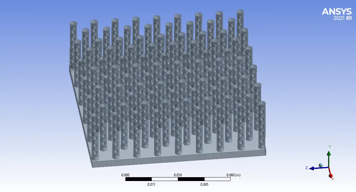
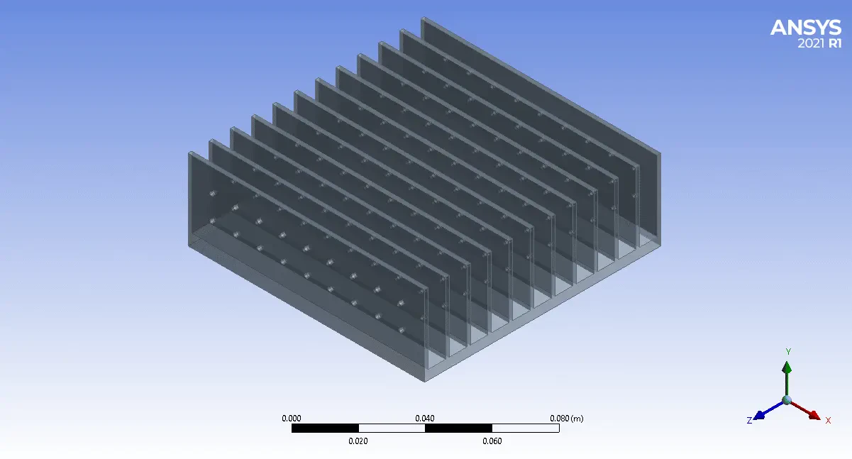
The system consists of four different heatsinks; heatsinks are in two general shapes one is a pin fin, and the other is a plate-fin; each shape has to case to study; one is the normal heatsink. The second one is with holes designed on their surface, and the goal of this study is to determine the absorbing effect of these holes and the total heatsink shape on their heat transfer rate.
Geometry & Mesh
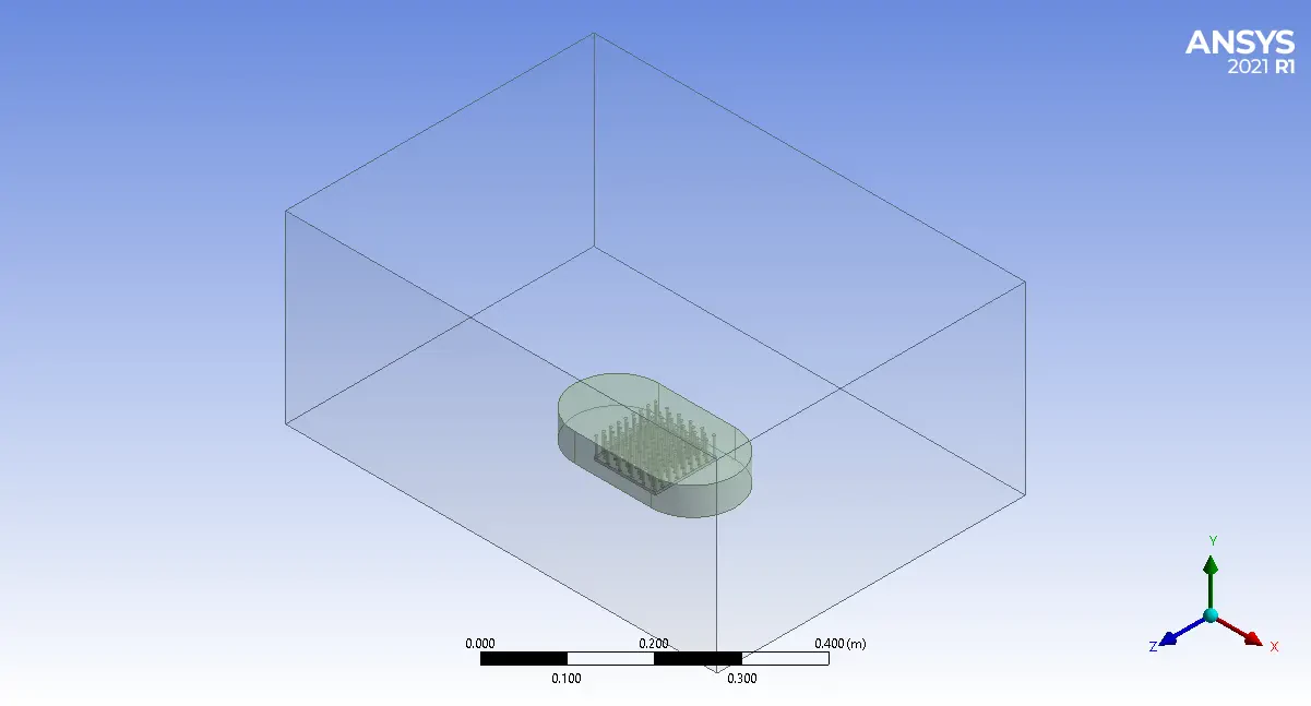
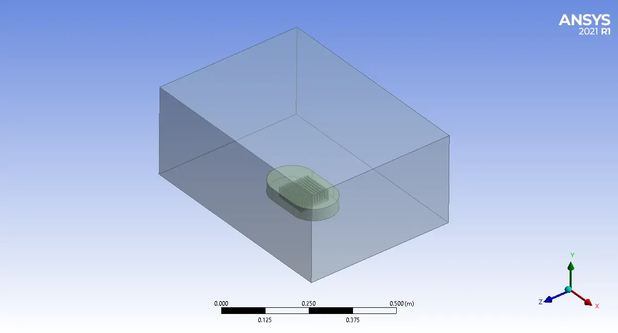
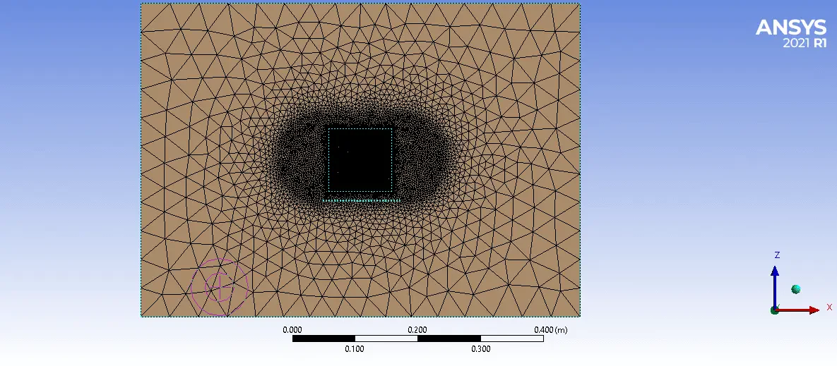
The 3-D domain of this simulation has been designed in ANSYS Design Modeler. The meshing of this present model has been generated by ANSYS Meshing software. The mesh grid is unstructured. The figure below shows an overview of the performed mesh.
CFD Simulation
To simulate the present model, several assumptions are considered, which are:
- The solver is pressure-based.
- The effect of gravity on the flow has been considered
- The hot zone wall model is considered a constant temperature
The following is a summary of the steps for defining the problem and its solution
| Models | ||
| k-omega | Viscous model | |
| SST | ||
| Pressure based | Solver | |
| steady | Time step | |
| Energy | on | |
| Boundary conditions | ||
| Velocity-inlet | Air inlet | |
| 0.1 m/s | Fluid inlet velocity | |
| 300 k | Temperature | |
| Pressure outlet | outlet | |
| 0 | Supersonic gage pressure | |
| wall | Sink wall | |
| stationary wall | wall motion | |
| heat flux | Thermal condition | |
| 2500 w | heat flux | |
| wall | hot wall | |
| stationary wall | wall motion | |
| 330 k | Temperature | |
Pin and Plate Heat Sink Heat Transfer Results
The results of the simulation show static temperature contours. The simulation results show that the hole-less sinks had a better performance level. This life is because it increases the useful surface due to the low thickness of the plates and pins. A hole-less plate heatsink has the highest heat transfer value of 10.986 watts, 10.5682 watts of heat transfer compared to a hole in its wall.
On the other hand, compared to plate and pin heatsinks, plate heatsinks have shown better heat transfer due to having a higher level. The pinhole heatsink transmits 8.61 watts of heat at the same 30 ° C temperature difference, outperforming the 8.52-hole perforated pin sink.