

Porous Chamber Heat Transfer CFD Simulation, Tutorial
Price: $16
The problem simulates the airflow and heat transfer inside a cube-shaped chamber consisting of a regular porous medium.
Porous Chamber Heat Transfer CFD Simulation, Tutorial
Price: $16
The problem simulates the airflow and heat transfer inside a cube-shaped chamber consisting of a regular porous medium.

Porous Chamber Considering Heat Transfer, ANSYS Fluent CFD Simulation Training
The problem simulates the airflow and heat transfer inside a cube-shaped chamber consisting of a regular porous medium by ANSYS Fluent software. The porous medium used in this chamber is in the form of rows and columns of several aluminum balls, the number of which is 343. These aluminum balls have a density of 2719 kg.m-3, a specific heat capacity of 871 j.kg-1.K-1, and thermal conductivity of 0.5 W.m-1.K-1.
The fluid in this chamber is air and there is no special air inlet and outlet for the chamber. The main purpose of this study is to investigate changes in air temperature inside the chamber under the influence of these items as a porous medium. In fact, the upper surface of the chamber has a constant temperature of 323 K and the lower surface has a constant temperature of 273 K, and the side walls are also insulated.
Porous Chamber Geometry & Mesh
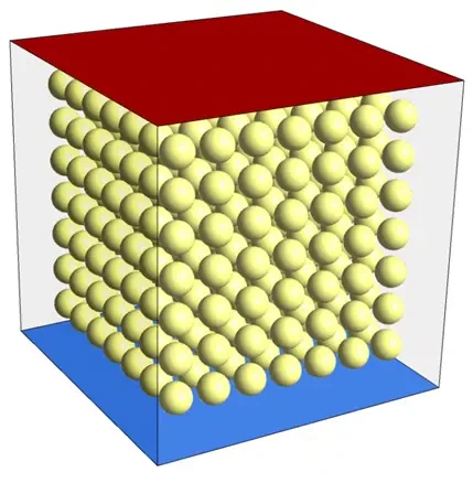
The present model is three-dimensional and is drawn using the ِ Design Modeler software. The present model is related to the chamber, which has seven spheres as a porous medium in three different directions. The total number of these spheres is 343. The figure below shows a view of the geometry.
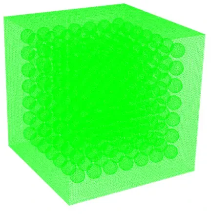
The meshing of the model has been done using ANSYS Meshing software and the mesh type is unstructured. The element number is 3451362. The figure below shows a view of the mesh.
Heat Transfer in a Porous Chamber CFD Simulation
To simulate the present model, several assumptions are considered:
- The solver is a pressure-based perspective.
- The present simulation is steady.
- The gravity of -9.81 m.s-2 is considered.
A summary of the steps for defining a problem and defining its solution is given in the following table:
| (Porous) | Models | |
| Viscous model | k-epsilon | |
| k-epsilon model | standard | |
| near-wall treatment | standard wall function | |
| Energy | on | |
| (Porous) | Boundary conditions | |
| down wall | Wall | |
| wall motion | stationary wall | |
| temperature | 273 K | |
| up wall | Wall | |
| wall motion | stationary wall | |
| temperature | 353 K | |
| sides walls | ||
| wall motion | stationary wall | |
| heat flux | 0 W.m-2 | |
| (Porous) | Solution Methods | |
| Pressure-velocity coupling | Coupled | |
| Spatial discretization | pressure | standard |
| density | second-order upwind | |
| momentum | second-order upwind | |
| energy | second-order upwind | |
| turbulent kinetic energy | first-order upwind | |
| turbulent dissipation rate | first-order upwind | |
| (Porous) | Initialization | |
| Initialization method | Standard | |
| gauge pressure | 0 Pa | |
| velocity (x,y,z) | 0 m.s-1 | |
| temperature | 298 K |
Results
At the end of the solution process, two-dimensional and three-dimensional contours of velocity, pressure, and temperature, as well as two-dimensional and three-dimensional velocity vectors are obtained.