

Rampressor, ANSYS Fluent CFD Simulation Training
Price: $36
The present problem simulates the air compression inside a Rampressor using ANSYS Fluent software.
Rampressor, ANSYS Fluent CFD Simulation Training
Price: $36
The present problem simulates the air compression inside a Rampressor using ANSYS Fluent software.
Project Description
The present problem simulates the air compression inside a Rampressor using ANSYS Fluent software. The Rampressor is a unique type of ultrasonic compressor rotor that operates at a high-pressure ratio, and engine technology and gas compression are the ramjet ultrasonic shock wave. The operating mechanism of these compressors is such that the gas flow passes through a fixed outer cover and a sloping surface or inner ramp; While this inner surface has a ramp with its rotational motion relative to the fixed body, it increases or decreases the gas passage. This change in the cross-section of the gas flow causes the shock wave phenomenon and changes the value of the Mach number, and thus causes the gas to condense.
In this simulation, the inner wall of the Rampressor rotates around its central axis (z-axis) at a rotational speed of 40,000 rpm. The frame motion technique is used to define this rotational motion; This means that the inner wall, called shroud, is assumed to have a rotational movement with a velocity of 0 rpm, and the inner part of this computational region, which is around this inner wall, has a rotational motion in the frame motion section with the same speed equal to 40,000 rpm. Due to the compressive nature of this Rampressor, the pressure boundary conditions at the inlet and outlet have been used. The air in these sections has a relative pressure equal to 104600 pascal and 35000 pascal.
Also, since the airflow inside this device is entirely compressible, the density-based solver has been used.
Rampressor Geometry & Mesh
The present model is designed in three dimensions using Design Modeler software. The design of this Rampressor is in the form of a three-dimensional ring, the sides of which are defined as input and output sections, and the outer wall is defined as static, and the inner wall with several sloping surfaces as rotating.
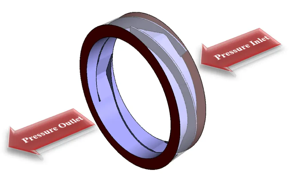
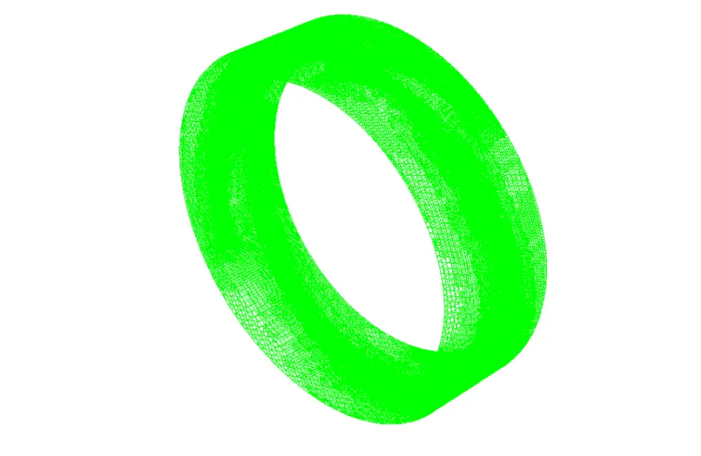
We carry out the model's meshing using ANSYS Meshing software, and the mesh type is unstructured. The element number is 1785931. The following figure shows the mesh.
Rampressor CFD Simulation
We consider several assumptions to simulate the present model:
- We perform a density-based solver.
- The simulation is steady.
- The gravity effect on the fluid is ignored.
The following table represents a summary of the defining steps of the problem and its solution:
| Models (Rampressor) | ||
| Viscous | k-epsilon | |
| k-epsilon model | standard | |
| near wall treatment | standard wall functions | |
| Energy | On | |
| Boundary conditions (Rampressor) | ||
| Inlet | Pressure Inlet | |
| gauge total pressure | 104600 pascal | |
| total temperature | 300 K | |
| Outlet | Pressure Outlet | |
| gauge pressure | 350000 pascal | |
| Shroud & Inner Wall | Wall | |
| wall motion | moving wall | |
| type of motion | rotational | |
| rotational speed | 0 rpm | |
| heat flux | 0 W.m-2 | |
| Methods (Rampressor) | ||
| Formulation | Implicit | |
| flow | first order upwind | |
| turbulent kinetic energy | first order upwind | |
| turbulent dissipation rate | first order upwind | |
| Initialization (Rampressor) | ||
| Initialization methods | Hybrid | |
Results & Discussions
At the end of the solution process, two-dimensional and three-dimensional contours related to pressure, velocity, density, temperature and Mach number are obtained. It can be seen from the pictures that the amount of pressure in the Rampressor outlet increases. Also, the amount of Mach number increases in the space between the ramps and the equipment body.