

Separator CFD Simulation, Three-Phase Flow, ANSYS Fluent Training
Price: $140
In this project, a 3-Phase Horizontal Separator with an Oil Bucket is simulated.
Separator CFD Simulation, Three-Phase Flow, ANSYS Fluent Training
Price: $140
In this project, a 3-Phase Horizontal Separator with an Oil Bucket is simulated.

Separator Problem Description
The 3-Phase Horizontal Separator works based on the density differences of fluids. The mixture of fluids inter through the inlet vessel and, after collision with the inlet diverter, enters the tank. In reality, the Separator is equipped with sensors to control oil and water level and then control mass flow.
Therefore, controlling the mass flows is a challenge in the simulation. In this project, the density of air, water, and oil is assumed to be 1.2, 998 & 689 kg/m^3, respectively. Also, the VOF Multiphase model is used.
Geometry & Mesh
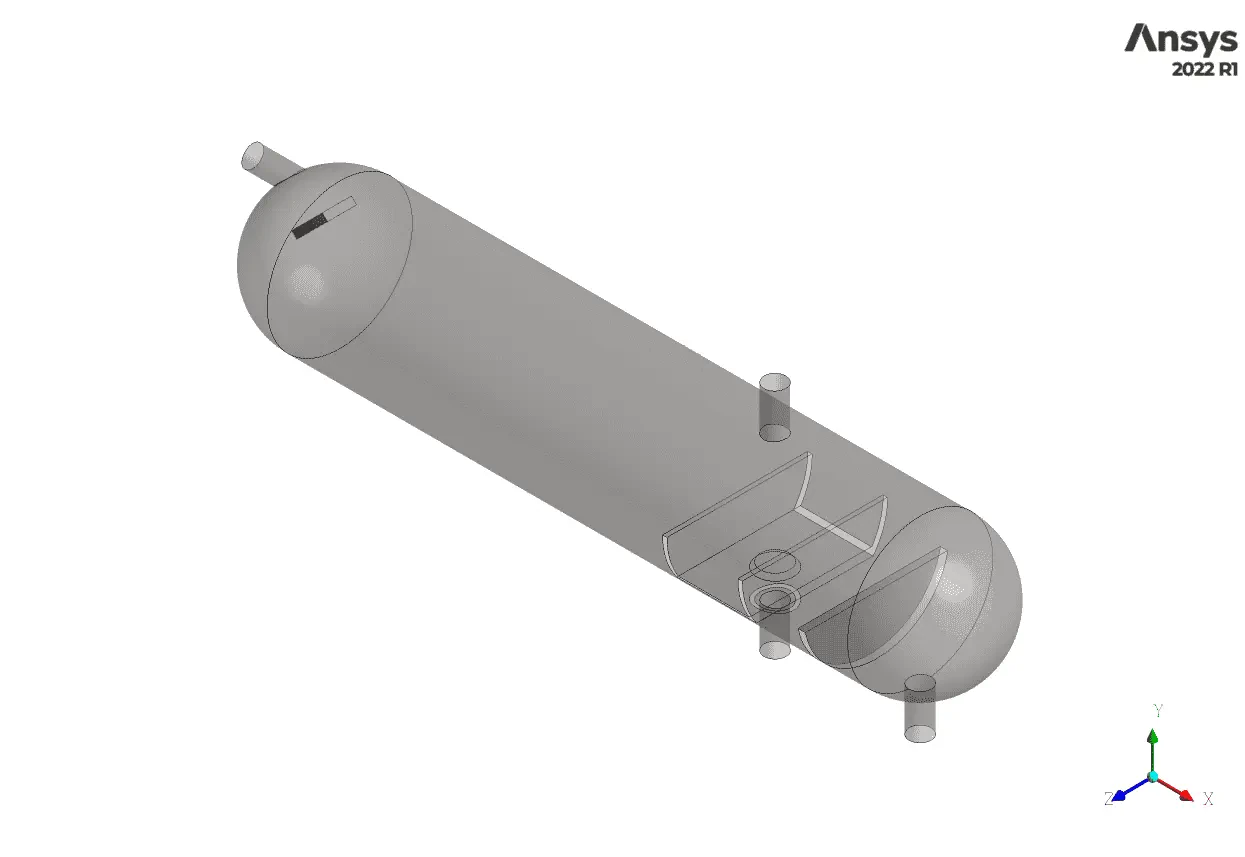
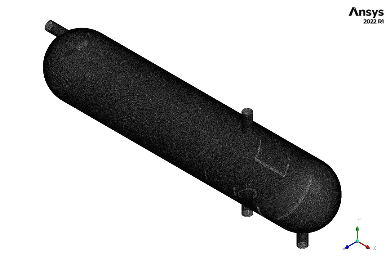
The 3D geometry is modeled in Ansys Design Modeler software. A cylindrical zone with a 1m diameter extended for 8 meters with two caps. Also, the mesh grid is carried out using Ansys Meshing software.
Furthermore, an unstructured grid is generated, and in total, 7166267 elements established the fluid domain, which is depicted in the following figure.
CFD Simulation
Several assumptions have been considered to simulate the horizontal 3-phase separator, including:
- The simulation is steady.
- The pressure-based solver type is used due to the incompressibility of the working fluids.
- Gravitational acceleration effects are applied in the y-direction.
The following table represents a summary of the solution:
| Models(Viscous) | ||
| Viscous | K-epsilon | Realizable |
| Multiphase | Type | VOF |
| Formulation | Implicit | |
| Primary Phase Secondary Phase Secondary Phase | Air Oil Water-liquid | |
| Materials | ||
| Fluid | Definition method | Fluent database |
| Material name | Air | |
| Engine-oil | ||
| Water-liquid | ||
| Cell zone condition | ||
| Material name | Mixture-template | |
| Boundary condition | ||
| Inlet | Type | Mass-flow-inlet |
| Gas-phase | 0.005 kg/s | |
| Oil-phase | 2 kg/s | |
| Water-phase | 3 kg/s | |
| Outlet-gas Outlet-oil Outlet-water Wall-shell Oil-Bucket Diverter Separator | Type | Mass-flow-outlet |
| 0.005 kg/s | ||
| Type | Mass-flow-outlet | |
| 2 kg/s | ||
| Type | Mass-flow-outlet | |
| 3 kg/s | ||
| Type | Wall (Stationary – No-slip condition) | |
| Solver configuration | ||
| Pressure-velocity coupling | Scheme | Coupled |
| Spatial Discretization | Gradient | Least squares cell-based |
| Pressure | PRESTO! | |
| Momentum | First-order upwind | |
| Volume Fraction | Modified HRIC | |
| Turbulent kinetic energy | First-order upwind | |
| Turbulent dissipation rate | First-order upwind | |
| Initialization | Initialization methods | Standard Initialization |
| Run Calculation | ||
| Number of time steps | 1000 | |
Separator Results
After the simulation process, the two & three-dimensional contours are extracted. It is evident that high inlet velocity could increase the mixing rate, which is not our interest and aim. So by using an inclined diverter, the velocity decreases and enters the fluid domain.
Due to the density gradient, the dense fluid (water) remains at the bottom of the tank, and the oil on the top reaches the oil bucket level and leaves the tank. The volume fraction contours corroborate the claim.