

Separator Two-Phase Flow, CFD Simulation ANSYS Fluent Training
Price: $48
The present problem simulates the collision of air and water flow within a separator chamber using ANSYS Fluent software.
Separator Two-Phase Flow, CFD Simulation ANSYS Fluent Training
Price: $48
The present problem simulates the collision of air and water flow within a separator chamber using ANSYS Fluent software.
Separator Project Description
The present problem simulates the collision of air and water flow within a separator chamber using ANSYS Fluent software. In this model, a cylindrical separator chamber is designed whose interior space is full of water.
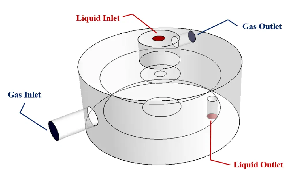
Water then enters through a vertical pipe from the top of the chamber and exits through a bottom pipe located at the bottom of the chamber; While airflow enters from a horizontal tube on the lateral surface of the chamber and exits through a horizontal tube on the lateral surface of the upper part.
The inlet air to the chamber has a mass flow rate of 0.001 kg.s-1 and the inlet water flow to the chamber has a mass flow rate of 0.1 kg.s-1.
Naturally, the water flow is located in the lower part of the chamber due to being denser and the airflow is located on the top of the water surface. Since there are two phases in this modeling, the multiphase model should be used.
For this reason, the VOF multiphase model is used in this modeling; So the primary phase is defined as water flow and the secondary phase is defined as airflow. Assuming that the water flow in the airflow is formed as a layer or free surface and does not mix with the airflow, the VOF model is the most appropriate model to define the present multiphase flow.
Also, the effect of surface tension between the two phases is defined and the amount of surface tension between the two phases of the water and air is defined as 0.072 N.m-1.
Separator Geometry & Mesh
The present model is designed in three dimensions using Design Modeler software. The model consists of a cylindrical chamber that has two inlet and outlet pipes for water flow vertically and two inlet and outlet pipes for air horizontally.
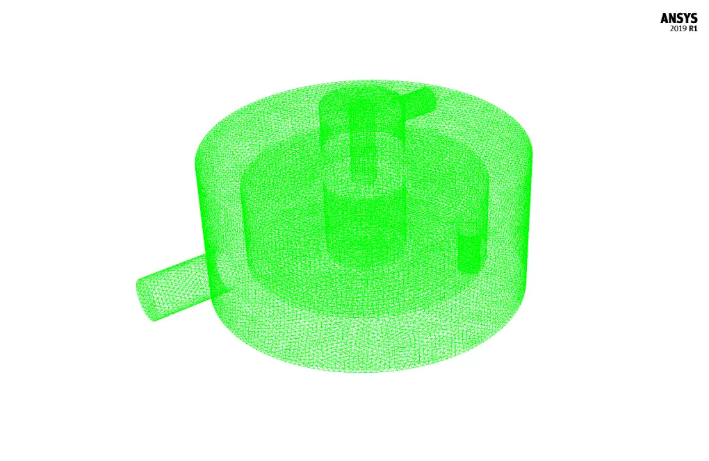
We carry out the model's meshing using ANSYS Meshing software, and the mesh type is unstructured. The element number is 972786. The following figure shows the mesh.
Separator CFD Simulation
We consider several assumptions to simulate the present model:
- We perform a pressure-based solver.
- The simulation is steady.
- The gravity effect on the fluid is equal to -9.81 m.s-2 along the vertical axis.
The following table represents a summary of the defining steps of the problem and its solution:
| Models | ||
| Viscous | k-epsilon | |
| k-epsilon model | standard | |
| near wall treatment | standard wall functions | |
| Multiphase Model | VOF | |
| number of eulerian phases | 2 (water & air) | |
| formulation | implicit | |
| interface modeling | dispersed | |
| Boundary conditions | ||
| Inlet - Gas | Mass Flow Inlet | |
| mass flow rate - water | 0 kg.s-1 | |
| mass flow rate - air | 0.001 kg.s-1 | |
| Inlet - Liquid | Mass Flow Inlet | |
| mass flow rate - water | 0.1 kg.s-1 | |
| mass flow rate - air | 0 kg.s-1 | |
| Outlet - Gas | Pressure Outlet | |
| gauge pressure | 0 pascal | |
| Outlet - Liquid | Pressure Outlet | |
| gauge pressure | 0 pascal | |
| Walls | Wall | |
| wall motion | stationary wall | |
| Methods | ||
| Pressure-Velocity Coupling | Coupled | |
| Pressure | PRESTO | |
| momentum | first order upwind | |
| turbulent kinetic energy | first order upwind | |
| turbulent dissipation rate | first order upwind | |
| volume fraction | first order upwind | |
| Initialization | ||
| Initialization methods | Standard | |
| gauge pressure | 0 Pascal | |
| velocity (x,y,z) | 0 m.s-1 | |
| air volume fraction | 0 | |
| water volume fraction | 1 | |
Results & Discussions
At the end of the solution process, two-dimensional and three-dimensional contours related to the mixing pressure and mixing velocity and volume fraction of each of the water and air phases are obtained. The images show that the airflow moves upwards because it is lighter and the water flow moves downwards because it is denser.