

Shell and Tube Heat Exchanger with a spiral Baffle
Price: $80
The problem simulates heat transfer inside a shell and tube heat exchanger with a spiral buffer.
Shell and Tube Heat Exchanger with a spiral Baffle
Price: $80
The problem simulates heat transfer inside a shell and tube heat exchanger with a spiral buffer.
Shell and Tube Heat Exchanger with a spiral Baffle, ANSYS Fluent CFD Simulation Training
The problem simulates heat transfer inside a shell and tube heat exchanger with a spiral buffer by ANSYS Fluent software. The heat exchanger is a device for transferring heat between two hot and cold fluids. The industry's two most common heat exchangers are plate heat exchangers and shell and tube heat exchangers. The shell and tube heat exchangers consist of a cylindrical outer shell and inner tubes inside.
One of the cold or hot fluids passes through the space between the tubes and the outer shell, and the other fluid passes through the inner space of the inner tubes in the same direction or vice versa. One way to enhance the heat transfer process between two fluids is to use buffers inside the shell's fluid flow path.
The use of buffers in the flow of fluid causes turbulence in the fluid flow through the shell and further contact of the fluid with the tubes, and as a result, heat transfer is enhanced; But on the other hand, it causes a pressure drop in the fluid as well as the deposition of fluid in the shell. Therefore, the use of helical baffle reduces the pressure drop and sedimentation inside the heat exchanger in addition to strengthening the heat transfer between the two fluids.
In the current model, the heat exchanger consists of seven internal tubes and a spiral buffer inside the shell. The flow of water with a flow rate of 0.5 kg.s-1 and a temperature of 300 K enters the shell from the shell inlet and is exchanged with tubes with a constant temperature of 450 K.
In fact, it is assumed that the cold flow passes through the shell and the hot flow through the inner tubes; But for simplicity, the model assumes that the temperature of the hot fluid flowing through the tubes during the process has a constant temperature value, which is assumed to be 450 K.
Shell and Tube HEX Geometry & Mesh
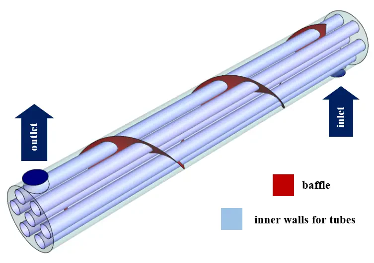
The present 3-D model is designed using Design Modeler software. The model is a shell and tube heat exchanger that includes an external shell and seven internal tubes inside. The diameter of the shell is 3 cm and its length is 60 cm. Inside the interior and between the shell and the tube, a spiral buffer is used. The following figure shows a view of the geometry.
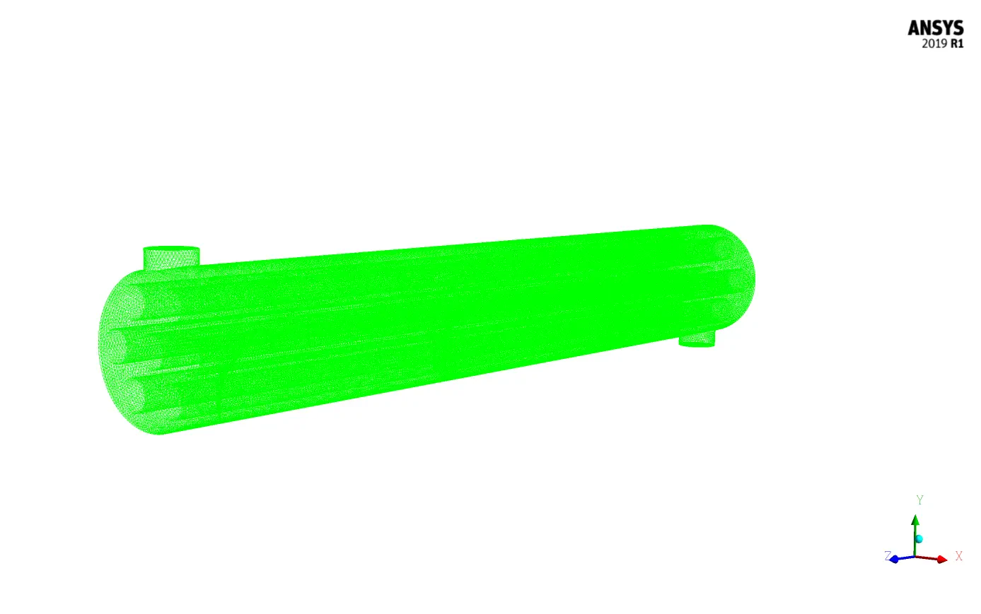
The meshing of the model has been done using ANSYS Meshing software and the mesh type is unstructured. The element number is 1629340 and the accuracy of the cells in the areas adjacent to the wall of the tubes is higher. The following figure shows a view of the mesh.
CFD Simulation
To simulate the present problem, several assumptions are considered:
- The simulation is steady-state.
- The solver is pressure-based.
- The effect of the gravity on the fluid flow is 9.81 m.s-2 along the y-axis downward.
A summary of the steps for defining the problem and its solution is given in the following table:
| Models (shell and tube) | |||
| k-epsilon | Viscous model | ||
| realizable | k-epsilon model | ||
| standard wall function | near-wall treatment | ||
| on | Energy | ||
| Boundary conditions (shell and tube) | |||
| mass flow inlet | Inlet | ||
| 0.5 kg.s-1 | mass flow rate | ||
| 300 K | temperature | ||
| Pressure outlet | Outlet | ||
| 0 Pa | gauge pressure | ||
| wall | Baffle's wall | ||
| stationary wall | wall motion | (shell and tube) | |
| coupled | thermal condition | ||
| Outer wall for shell | |||
| stationary wall | wall motion | ||
| 0 W.m-2 | heat flux | ||
| wall | Inner walls for tubes | ||
| stationary wall | wall motion | ||
| 450 K | temperature | ||
| Solution Methods (shell and tube) | |||
| Simple | Pressure-velocity coupling | ||
| Standard | pressure | Spatial discretization | |
| first-order upwind | momentum | ||
| first-order upwind | turbulent kinetic energy | ||
| first-order upwind | turbulent dissipation rate | ||
| first-order upwind | energy | ||
| Initialization (shell and tube) | |||
| Standard | Initialization method | ||
| 0 Pa | gauge pressure | ||
| 0 m.s-1 | x-velocity, z-velocity | ||
| 0.7106586 m.s-1 | y-velocity | ||
| 300 K | temperature | ||
Shell and Tube Results
At the end of the solution process, two-dimensional and three-dimensional contours of pressure, temperature, and velocity, as well as two-dimensional and three-dimensional velocity vectors and path lines, are obtained.