

Shrouded Micro-wind Turbine CFD Simulation, Paper Numerical Validation, ANSYS Fluent
Price: $32
- The current CFD Analysis numerically Validates the Paper "Experimental study of shrouded micro-wind turbine" via ANSYS Fluent software.
- We have designed and meshed the geometry using Design Modeler and ANSYS Meshing then meshing in fluent, producing 2,356,897 polyhedral elements.
- MRF is used to simulate rotating zone.
- The turbulence of the flow is simulated via K-w sst model.
Description
This product is validation of simulating a shrouded micro-wind turbine based on the paper "Experimental study of shrouded micro-wind turbine" by ANSYS Fluent software.
Shrouded micro-wind turbines, also known as ducted wind turbines, feature a design that incorporates a shroud or duct surrounding the turbine blades. This shroud is engineered to increase the wind velocity passing through the rotor, which in turn boosts the turbine's power output. The principle behind this technology is based on the Bernoulli's principle and the Venturi effect, where the shroud acts as a diffuser and an accelerator for the wind. The narrowed part of the shroud accelerates the wind before it hits the blades, enhancing the turbine's efficiency compared to traditional open-bladed turbines. These turbines are compact, making them suitable for small-scale energy generation projects with lower environmental impact and visual intrusion.
The geometry is designed in Design Modeler then meshed in ANSYS Meshing with 11,581,035 tetrahedral cells. Then, by entering the grid in the Fluent software, the grid is converted into 2,356,897 polyhedral elements which has a lower number of elements and a higher quality.
Methodology
Around the blades a cylindrical domain is defined as the moving part which is simulated by MRF assuming turbine axes of the computing domain are rotating instead of moving mesh. The air passes over the turbine and duct at a speed of 5m/s, and the speed of rotation of the turbine is considered 2010.3 rpm. Also the turbulence of the flow is simulated via K-w sst model.
Conclusion
To verify the accuracy of the simulation of this wind turbine with the results in the article, the value of Cp should be defined as the output in the simulation and then compared this number and its difference. T means the torque around the blade, w is the amount of rotation of the turbine, U and A is the average speed value in the flow direction and the average area at the nozzle exit, respectively.
A point is selected as desired (for example, h/d=0.2 and λ=4) and then the value of the revolution and speed of the turbine is determined based on this.
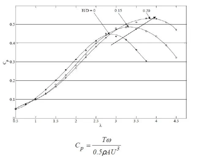
According to the result presented in the table of the Cp value of the article with simulation, at this point there is a very small difference between the presented state and the simulation solution.
| Experiment | simulation | E% | |
| Cp | 0.525 | 0. 456 | -13.1% |