

Slat and Flap Devices Effects on an Aircraft Wing
Price: $20
The present problem simulates the airflow around the aircraft wing with a flap and slat, using ANSYS Fluent software.
Slat and Flap Devices Effects on an Aircraft Wing
Price: $20
The present problem simulates the airflow around the aircraft wing with a flap and slat, using ANSYS Fluent software.
Slat and Flap Devices Effects on an Aircraft Wing, ANSYS Fluent Training
The present problem simulates the airflow around the aircraft wing with a flap and slat, using ANSYS Fluent software. In this project, a 3D airplane wing is designed; In such a way, a Flap is on the trailing edge, and a Slat is on the leading edge of the wing.
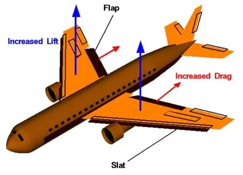
A flap is a small aerodynamic surface placed on the trailing edge of an aircraft wing to increase the lift force on the aircraft wing. Lift force is the main factor holding the aircraft in the air and overcoming the force of the aircraft's weight. Lift force is directly related to the aircraft's speed; As the aircraft speed increases, the lift force is amplified, and as the aircraft speed decreases, the lift force decreases. Therefore, when the aircraft's speed is reduced, such as when the aircraft takes off or lands, the lift force decreases, and, as a result, the lift force must be strengthened. Therefore, the flap is used on the fuselage of the aircraft wing to compensate for this decrease in lift force by rotating around its axis at the trailing edge and increasing the contact surface of the wing with the airflow.
A slat is a small aerodynamic surface that sits on the leading edge of an aircraft wing. Similarly, the air is used at the wing leading edge to increase the lift force when the aircraft speed slows down, such as when the aircraft takes off or lands. The Slat rotates around its axis at the wing leading edge and increases the wing contact surface with the air stream. Also, the slat can increase the area of the aircraft wing, increase the drag force and help the aircraft land more slowly during landing.
The airflow in the vicinity of the aircraft wing is compressible. This simulation is based on a density-based solver. Also, due to the compressibility of the airflow, the ideal gas model has been used to define the amount of airflow density changes.
In terms of boundary conditions, airflow velocity in the computational area around the wing is 271.958 m.s-1 along the x-axis and 40.79 m.s-1 along the y-axis. Also, the airflow temperature is equal to 305.5 K.
Geometry & Mesh
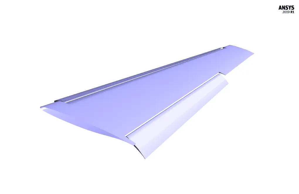
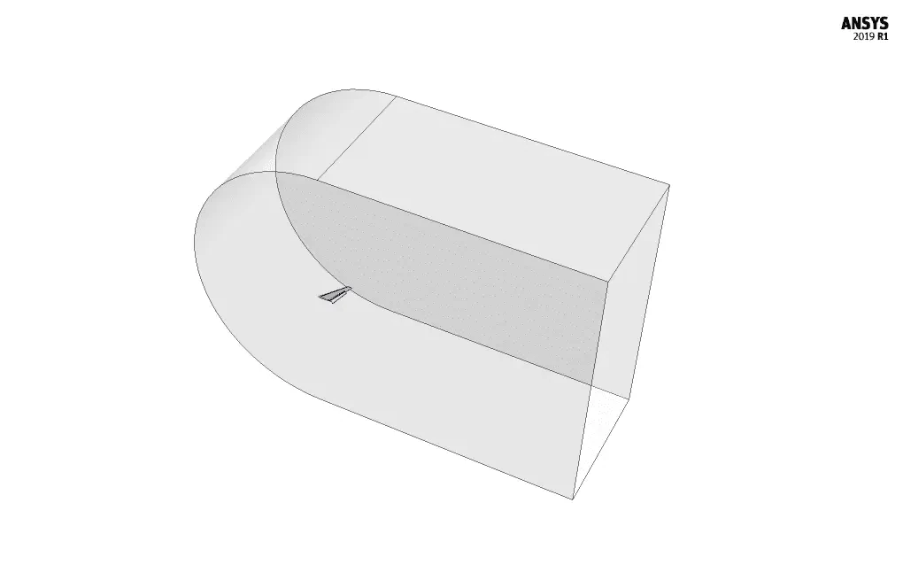
The present model is designed in three dimensions using Design Modeler software. The model is a wing of an aircraft with an Slat on the leading edge and a Flap on the trailing edge.
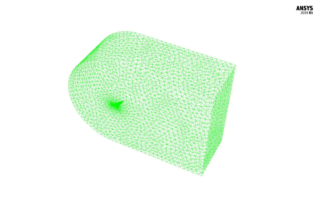
We carry out the model's meshing using ANSYS Meshing software, and the mesh type is unstructured. The element number is 5658021. The following figure shows the mesh.
CFD Simulation
We consider several assumptions to simulate the present model:
- We perform a density-based solver.
- The simulation is steady.
- The gravity effect on the fluid is ignored.
The following table represents a summary of the defining steps of the problem and its solution:
| Models | ||
| Viscous | k-epsilon | |
| k-epsilon model | Spalart-Allmaras | |
| Boundary conditions | ||
| Inlet | Velocity Inlet | |
| x-velocity | 271.958 m.s-1 | |
| y-velocity | 40.79 m.s-1 | |
| temperature | 305.5 K | |
| Outlet | Pressure Outlet | |
| gauge pressure | 0 pascal | |
| Walls (wing, flap, slat) | Wall | |
| wall motion | moving wall | |
| heat flux | 0 W.m-2 | |
| Symmetry | Symmetry | |
| Methods | ||
| Formulation | implicit | |
| flow | second-order upwind | |
| modified turbulent viscosity | second-order upwind | |
| Initialization | ||
| Initialization methods | Standard | |
| gauge pressure | 0 pascal | |
| x-velocity | 271.958 m.s-1 | |
| y-velocity | 40.79 m.s-1 | |
| z-velocity | 0 m.s-1 | |
| temperature | 305.5 K | |
Results & Discussions
At the end of the solution process, two-dimensional counters of pressure, temperature, velocity, Mach number, and density are obtained perpendicular to the plane of the airflow area adjacent to the fuselage. Two-dimensional path lines and two-dimensional velocity vectors are also obtained on the same plane. Also, a pressure contour is obtained on the surface of the fuselage. The contours clearly show changes in velocity, density, and airflow pressure around the fuselage. This indicates the occurrence of a pressure difference and the creation of a lift force. Also, the comparison of the contour of pressure on the aircraft's fuselage from the two upper and lower views of the aircraft shows the production of lift force against the force of weight.