

Sloshing Tank, ANSYS Fluent CFD Simulation Training
Price: $99
- The Sloshing fluid CFD simulation in a tank containing LNG fuel and air by ANSYS Fluent software.
- The geometry of the 2-D tank is modeled by Design Modeler software.
- A structured mesh is done for the sloshing tank by ANSYS Meshing software.
- The simulation is Transient.
- The Frame Motion (MRF) method applying a UDF for the sloshing movement is used.
- The Multiphase VOF model is applied to model the air and fluid.
Sloshing
Experimental and numerical studies show the importance of the effect of fluid sloshing within the tank on the maneuverability of the floating devices like ships, boats, and so on. Among the most important laboratory studies, we can point:
1- Measuring the sloshing dynamics of a tank
2. Experimental-Statistical Study of Sloshing Wave Impact Loads in the Shell Tank Model
3. Verification of numerical sloshing results of the floating device containing natural gas tank using an experimental result on a two-dimensional section of the reservoir at a scale of 0.1 at two different filling heights.
4. Investigate the maximum long-term sloshing pressures applied to the shell tank in order to consider the effects of the vibration caused by the bump.
5- Experimental study of pressure distribution due to the liquid sloshing in a rectangular tank
Tank Geometry
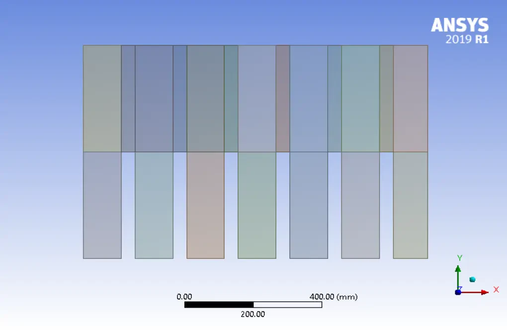
The initial stage of any simulation is devoted to the design of solution geometry or computational domain modeling. The computational domain in Sloshing CFD simulation is a tank containing LNG fuel and air. The tank uses several series of joints and inner walls to prevent fluid movement. This results in less friction of the fluid layers over each other, as the inertia of the fluid moving inside the tank can have an effect on the fuel carrier vehicle. The model of the 2-D tank is modeled by Design Modeler software. The tank geometry is 1 m long and 0.7 m wide. Six rows of 0.35 m high and 0.04 m thick were used to separate the fluid layers. The geometry is divided for structured mesh applications.
Mesh
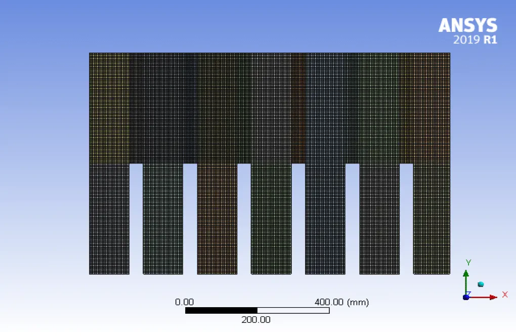
Since ANSYS Fluent software uses the finite volume method, it is important to have a high quality mesh. A structured mesh is done for sloshing tank by ANSYS Meshing software.
CFD Simulation
Once the mesh is loaded onto the ANSYS Fluent software, the solution process begins. This process involves defining the problem to the software. This table is a summary of Sloshing Tank CFD Simulation.
| Solver settings (sloshing tank): | |
| Type: | Pressure-based |
| Velocity formulation: | Absolute |
| Time setting: | Transient : Time-step : 0.005 s |
| Gravity: | On : -9.81 m/s2 in Y-direction |
| Energy: | off |
| Zone: | Frame Motion UDF #include "udf.h" DEFINE_ZONE_MOTION(NEWMOTION,omega,axis,origin,velocity,time,dtime) { N3V_D (velocity,=,0.5*sin(10*time),0.0,0.0); N3V_S(origin,=,0.0); /* default values, line could be omitted */ N3V_D(axis,=,0.0,0.0,1.0); /* default values, line could be omitted */ } |
| Boundary conditions: | Walls: No-slip |
| Operating Condition: | Reference Pressure Point: X : 0.00 m Y : 0.25 m Gravity: On : -9.81 m/s2 in Y-direction |
| Solution methods for sloshing CFD simulation: | SIMPLE |
| Pressure interpolation scheme: | PRESTO |
| Momentum: | QUICK |
| Level set implementation: | QUICK |
| VOF implementation: | Compressive |
| Relaxation: | Default |
| Initialization: | Standard All Zero Patch: Region X: -10 m to +10 m Y: 0 to 0.25 m Pressure static: Rhow*g*(1-y/Hw) Water VF: 1.0 |
Multi-phase (sloshing tank) : | |
| VOF : | Enabled |
| Formulation: | Implicit |
| Interface Modeling: | sharp |
| Implicit Body Force: | On |
| Open channel flow: | Off |
| Level Set | On |
| Phase-Interaction (sloshing tank): | |
| Surface tension Coeff (air-water): | 0.0725 n/m |
| Material used for sloshing tank CFD simulation : | |
| Fluid: | Air : Primary phase Water : Secondary phase |
| Monitor : | Point: Static Pressure: 0.0525 m |