

Spillway (Wide-Edge) with Lateral Slope, Two-Phase Flow, ANSYS Fluent
Price: $28
In this analysis, the flow inside a wide-edge spillway is investigated.
Spillway (Wide-Edge) with Lateral Slope, Two-Phase Flow, ANSYS Fluent
Price: $28
In this analysis, the flow inside a wide-edge spillway is investigated.
Introduction
A wide-edge spillway is a cascading structure with a long horizontal crown in the direction of the flow so that the error due to the distribution of hydrostatic pressure on it can be neglected due to the acceleration of the radial flow. These overflows operate in such a way that the flow upstream will be subcritical and supercritical on the spillway itself. As a result, a flow control section is created above it. One of the characteristics of such overflows is that in a short distance from the overflow crown, the flow lines are almost parallel.
In this type of spillway, the edge of the spillway is wide enough and has a considerable size compared to other dimensions. The crowns of the overflow edges are wide, horizontal or have a special curvature. Although they are also used to measure discharge, they are mostly used as dam overflows and sometimes as the dam itself (if water is allowed to pass through it) and can be used to store large volumes of water when necessary.
Project description
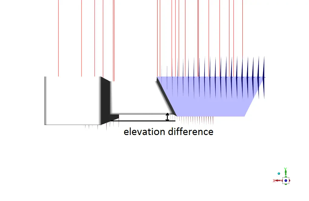
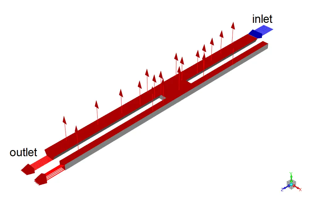
In this analysis, the flow inside a wide-edge spillway is investigated by ANSYS Fluent software. It should be pointed out that there is an elevation difference between the main and sub-channel for reasons like storing a portion of flowing water. The RNG k-epsilon model is used for solving turbulent flow equations. Also, multiphase VOF model is activated to simulate two phases of water and air inside the open channel. The water enters the open channel with a mass flow rate of 65Kg/s and enters the second channel after colliding with middle section of the spillway.
Geometry and mesh
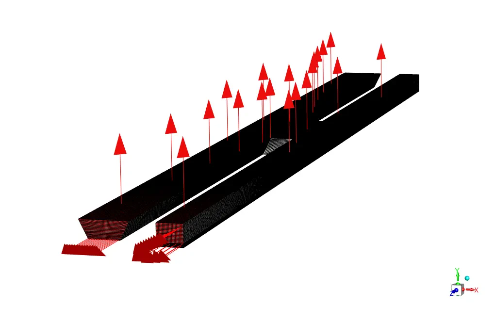
The geometry of this project is designed and meshed inside ANSYS design modeler and meshed in ANSYS meshing. The meshes type used for this geometry is structured and the total number of elements is 981900.
Spillway CFD simulation settings
The key assumptions considered in this project are:
- Simulation is done using pressure-based solver.
- The present simulation and its results are considered to be steady and do not change as a function time.
- The effect of gravity has been taken into account and is equal to -9.81 in Y direction.
The applied settings are recapitulated in the following table.
| Models | ||
| Viscous model | k-epsilon | |
| k-epsilon model | RNG | |
| near wall treatment | standard wall function | |
| Multiphase | VOF | |
| Primary phase | Air | |
| Secondary phase | water | |
| Boundary conditions | ||
| Inlet | ||
| Water inlet | Type | Mass flow inlet |
| Mass flow rate | 65 Kg/s | |
| Open channel | ||
| Free surface level | 0.08 m | |
| Bottom level | 0 m | |
| Density interpolation method | From neighboring cell | |
| Outlets | Pressure outlet | |
| Walls | ||
| wall motion | stationary wall | |
| Solution Methods | ||
| Pressure-velocity coupling | SIMPLE | |
| Spatial discretization | pressure | PRESTO! |
| momentum | second order upwind | |
| Volume fraction | first order upwind | |
| turbulent kinetic energy | first order upwind | |
| turbulent dissipation rate | first order upwind | |
| Initialization | ||
| Initialization method | Standard | |
| gauge pressure | 0 Pa | |
| velocity | 0 m/s-1 | |
| Turbulent kinetic energy | 1 m2/s2 | |
| Turbulent dissipation rate | 1 m2/s3 | |
| Water volume fraction | 0 | |
Spillway Results
We can see in the water volume fraction contour that due to the existence of height difference and the lack of any inlet flow inside the sub-channel, the water volume fraction has values other than zero in the upper part of the sub-channel. After the simulation process, we extracted and presented 3D contours of pressure, velocity, volume fractions, etc.