

Stepped Spillway (Stair Spillway) CFD Simulation, ANSYS Fluent Training
Price: $28
In this analysis, two-dimensional simulation of a stepped spillway by ANSYS Fluent software is presented.
Stepped Spillway (Stair Spillway) CFD Simulation, ANSYS Fluent Training
Price: $28
In this analysis, two-dimensional simulation of a stepped spillway by ANSYS Fluent software is presented.
Stepped Spillway Introduction
Stepped spillway is commonly used in reservoir dams in order to release flood safely. The stairs of spillway increase energy dissipation greatly. Stair spillways are among the hydraulic structures which attracted great interest to the designers due to their high water capacity energy dissipation. The flow mechanism is complicated in such structures, and more research is being done about it. For this reason, more research and simulation are needed to understand the fluid flow pattern correctly.
Stair Spillway Project description
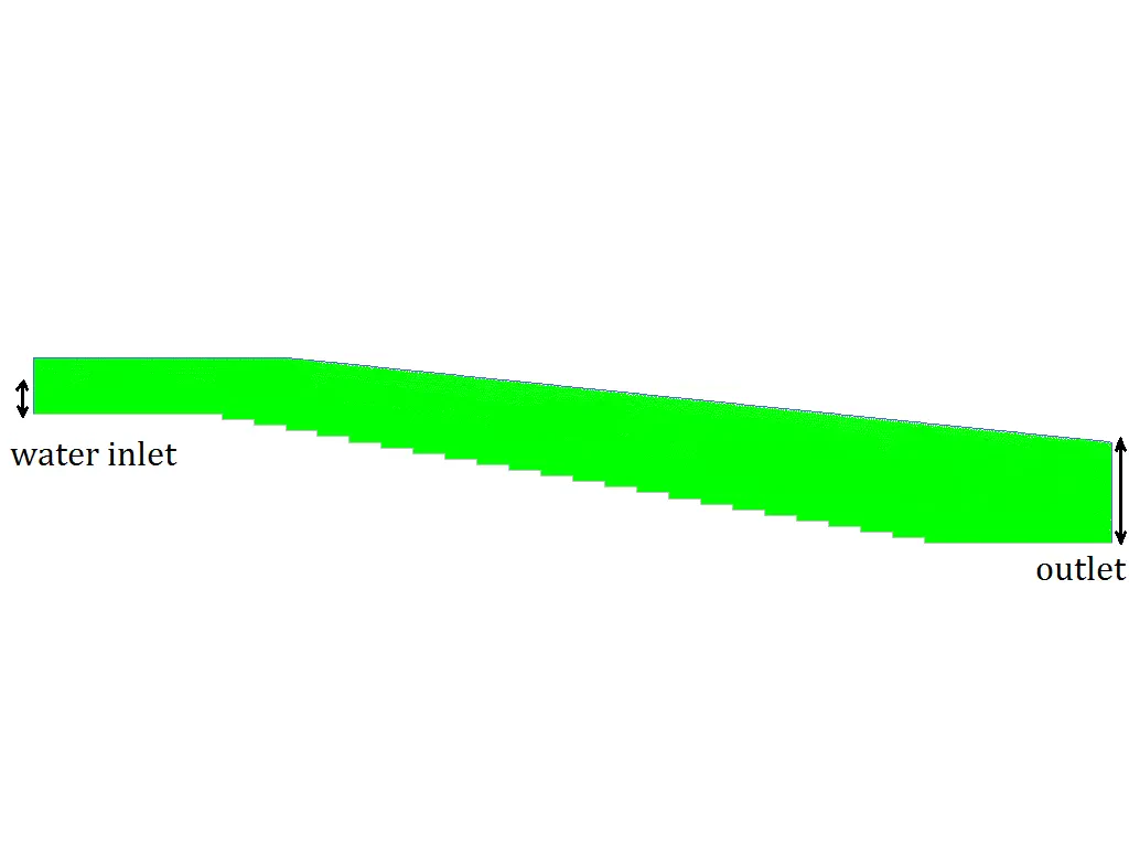
In this analysis, two-dimensional simulation of a stepped spillway by ANSYS Fluent software is presented. VOF model is activated for two phases of air and water and standard k-e model with the use of standard wall function is exploited for fluid flow analysis.
Stepped Spillway Geometry & Mesh
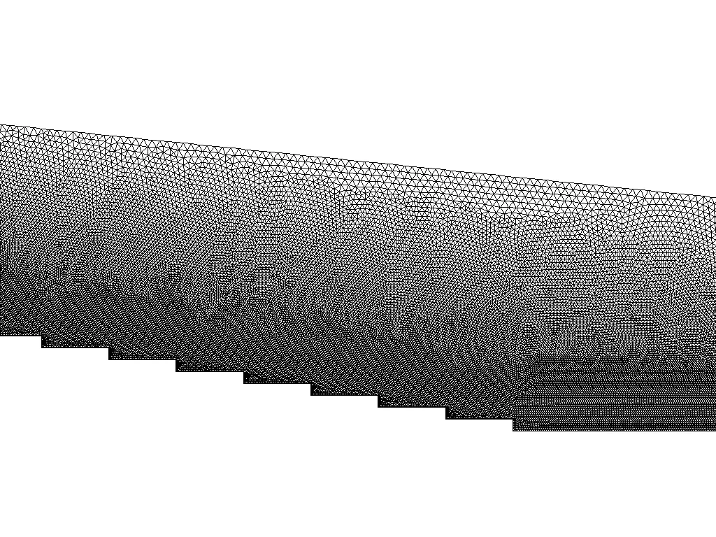
The modeled geometry is designed and meshed inside Gambit®. The mesh type used for this geometry is unstructured and the element number is 139067.
CFD Simulation Settings
The key assumptions considered in this project are:
- Simulation is done using pressure-based solver.
- The present simulation and its results are considered to be steady and do not change as a function time.
- The effect of gravity has been taken into account and is equal to -9.8 m/s2 in Y direction.
The applied settings are summarized in the following table.
| (stepped spillway) | Models | |
| Viscous model | k-epsilon | |
| k-epsilon model | standard | |
| near wall treatment | standard wall function | |
| Multi phase | VOF | |
| Phase 1 | Air | |
| Phase 2 | Water | |
| (stepped spillway) | Boundary conditions | |
| Inlets | velocity inlet | |
Water inlet | velocity | 1 m/s |
| Turbulent kinetic energy | 1 m2/s2 | |
| Turbulent dissipation rate | 1 m2/s3 | |
| Outlets | Pressure outlet | |
| Walls | ||
| wall motion | stationary wall | |
| (stepped spillway) | Solution Methods | |
| Pressure-velocity coupling | Simple | |
| Spatial discretization | pressure | PRESTO! |
| Volume fraction | first order upwind | |
| momentum | first order upwind | |
| turbulent kinetic energy | first order upwind | |
| turbulent dissipation rate | first order upwind | |
| (stepped spillway) | Initialization | |
| Initialization method | Standard | |
| gauge pressure | 0 Pa | |
| velocity (x,y,z) | (1,0,0) m/s | |
| Turbulent kinetic energy | 0 m2/s2 | |
| Turbulent dissipation rate | 1 m2/s3 | |
| Water volume fraction | 0 | |
Results
The contours of pressure, velocity, volume fraction, streamlines and velocity vectors are presented.