

Submarine Robot motion in a Water Channel, Dynamic Mesh, ANSYS Fluent
Price: $21
The present problem simulates the movement of a submarine robot inside a canal containing water flow using ANSYS Fluent software.
Submarine Robot motion in a Water Channel, Dynamic Mesh, ANSYS Fluent
Price: $21
The present problem simulates the movement of a submarine robot inside a canal containing water flow using ANSYS Fluent software.

Project Description
The present problem simulates the movement of a submarine robot inside a canal containing water flow using ANSYS Fluent software. The dynamic mesh method has been used to simulate the horizontal movement of this robot inside the channel. In this simulation, a two-dimensional channel is designed to flow at a speed of 1.5 m.s-1. Simultaneously, the robot inside the canal moves horizontally in the water flow path at a speed of 3 m.s-1. Due to the fact that this robot is moving within the computational domain and thus affects the grids around it, so we need a momentary and time-dependent change in meshing based on the type of displacement in the adjacent boundaries of grids.
Therefore, to define the instantaneous change of meshing, the Dynamic Mesh model has been used. In the determination of dynamic mesh methods, smoothing and remeshing methods have been used. According to the smoothing method, the number of nodes connections does not change and only adjusts the mesh of an area by moving or deforming the borders. The remeshing method, on the other hand, is used when the displacement of the borders is large relative to the size of the local cells to regenerate the destructive cells of the critical size limit.
(Project Description)
In the definition of areas under the dynamic mesh, the wall part of the robot is defined as a rigid body. This means that the robot's body acts as a rigid and integrated body and can be moved rotationally. This rigid body behavior means that the body itself does not change and only the meshing of the surrounding areas changes over time. Since the robot only moves horizontally at a certain speed, a profile is used to define this type of movement. This profile indicates the speed of the robot in the horizontal direction at different times. Due to the dependence of the dynamic mesh method over time, the present simulation process is defined as unsteady; So that the simulation is done in 1.5 seconds with a time step equal to 0.005 seconds.
Submarine Robot Geometry & Mesh
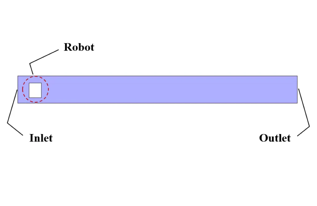
The present model is designed in two dimensions using Design Modeler software. The model is a two-dimensional channel in which a rectangular robot is placed. The channel has a length of 5 m and a width of 0.5 m. Also, the robot inside the channel has a length and width of 0.22 m and 0.27 m, respectively.
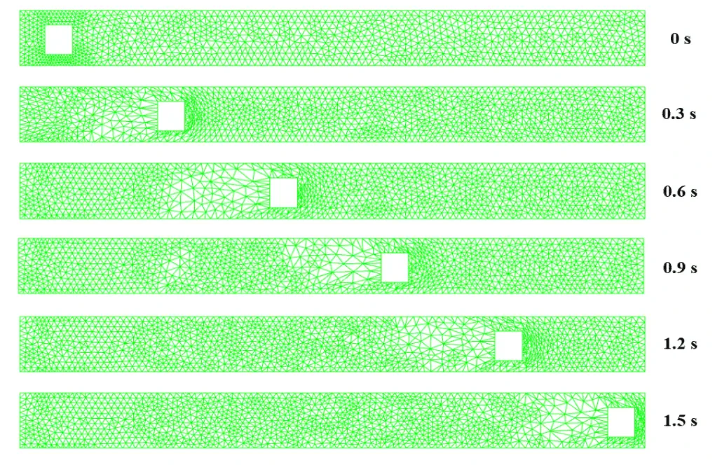
We carry out the model's meshing using ANSYS Meshing software. The mesh type is unstructured. The element number is 5924. To better understand the mesh changes over time due to the use of the dynamic mesh method, we present several views for meshing at different times.
Submarine Robot CFD Simulation
We consider several assumptions to simulate the present model:
We perform a pressure-based solver.
The simulation is unsteady.
We ignore the gravity effect.
The following table represents a summary of the defining steps of the problem and its solution:
| Models | ||
| Viscous | k-epsilon | |
| k-epsilon model | standard | |
| near wall treatment | standard wall function | |
| Dynamic Mesh | On | |
| mesh methods | smoothing & remeshing | |
| Boundary conditions | ||
| Inlet | Velocity Inlet | |
| velocity magnitude | 1.5 m.s-1 | |
| Outlet | Pressure Outlet | |
| gauge pressure | 0 pascal | |
| Walls | Wall | |
| wall motion | stationary wall | |
| Methods | ||
| Pressure-Velocity Coupling | SIMPLE | |
| pressure | second order | |
| momentum | second order upwind | |
| turbulent kinetic energy | first order upwind | |
| turbulent dissipation rate | first order upwind | |
| Initialization | ||
| Initialization methods | Standard | |
| gauge pressure | 0 pascal | |
| velocity (x,y) | 0 m.s-1 | |
Results
At the end of the solution process, we obtain two-dimensional contours related to velocity and pressure. Because the simulation is transient, we obtain contours at different times to compare the results over time. The contours show well that the robot in the channel has a horizontal movement and, over time, moves inside the channel containing the water flow. Also, due to the presence of the submarine robot body as a barrier in the flow of water inside the canal, a high-pressure area is created behind the submarine robot, and a high-speed area is created in front of it.