Transonic Linear Turbine Cascade at Off-Design Conditions, Paper Numerical Validation
Price: $32
The present project's results are compared with the experimental results of the paper “Midspan Flow-Field Measurements for Two Transonic Linear Turbine Cascades at Off-Design Conditions”. Turbulence modeling and Computational procedures (boundary conditions, etc.) are simulated based on the article “Numerical study of the flow field through a transonic linear turbine cascade at design and off-design conditions”.
Paper Description
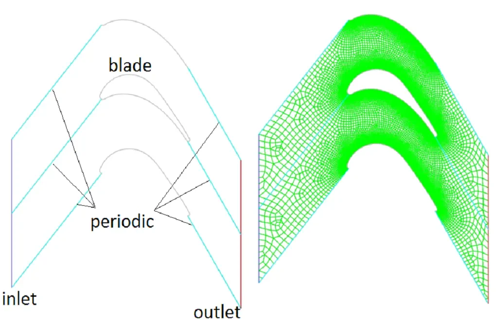
The present problem simulates the two-dimensional compressible flow field through a transonic linear turbine cascade. The present project's results are compared with the experimental results of the paper “Midspan Flow-Field Measurements for Two Transonic Linear Turbine Cascades at Off-Design Conditions.” Turbulence modeling and Computational procedures (boundary conditions, etc.) are simulated based on the article “Numerical study of the flow field through a transonic linear turbine cascade at design and off-design conditions.” In this project, inlet and outlet boundaries were considered as pressure inlet and pressure outlet, respectively, and Periodic boundary conditions were applied to simulate flow through the cascade.
In both references, the ratio of exit static pressure to inlet total pressure (P2/Pt1) was specified, but the total pressure and temperature were not specified. Therefore, at the inlet, the total pressure (Pt1) of 50KPa and the total temperature (Tt1) of 288K were considered, and the static pressure was calculated by the given pressure ratio in the papers. Also, the standard k-ε model and standard wall function were used to predict turbulent quantities. The density-based solver was selected due to the compressibility of flow. It should be noted that the ideal gas model was exploited to account for the airflow density changes due to the temperature changes.
Transonic Linear Turbine Cascade Geometry & Mesh
The geometry of this model is designed in ANSYS design modeler® and is meshed in ANSYS meshing®. The mesh type used for this geometry is structured and the element number is 27066. Also, the mesh cells around the blades are smaller to make the results more accurate.
Transonic Linear Turbine Cascade CFD simulation settings
The key assumptions considered in this project are:
- Simulation is done using density-based solver.
- The present simulation and its results are steady.
- The effect of gravity has been ignored.
The applied settings are summarized in the following table.
| Models | ||
| Viscous model | k-epsilon | |
| k-epsilon model | Standard | |
| Wall treatment | Standard wall function | |
| Energy model | On | |
| Boundary conditions | ||
| Inlet | Pressure inlet | |
| Gauge pressure | 50 kPa | |
| Supersonic/initial gauge pressure | 500 kPa | |
| Temperature | 288 K | |
| Outlets | Pressure outlet | |
| Gauge pressure | 35200 Pa | |
| Temperature | 288 K | |
| Walls | ||
| wall motion | stationary wall | |
| Heat flux | 0 W/m2 | |
| Solution Methods | ||
| Formulation | Implicit | |
| Flux type | Roe-FDS | |
| flow | first order upwind | |
| Turbulent kinetic energy | first order upwind | |
| Specific dissipation rate | first order upwind | |
| Initialization | ||
| Initialization method | Hybrid | |
Paper Results
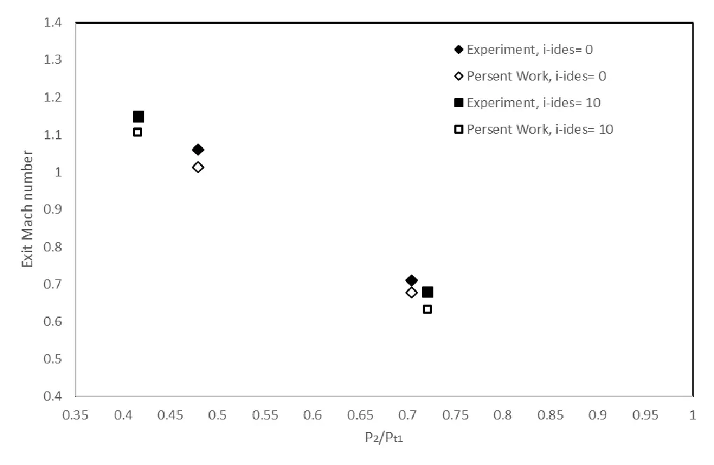
At the end of this simulation, the results of the present work are compared with results obtained by the paper. For this purpose, the diagram in figure 7 and, Table 5 of the paper "Midspan Flow-Field Measurements for Two Transonic Linear Turbine Cascades at Off-Design Conditions" were used.
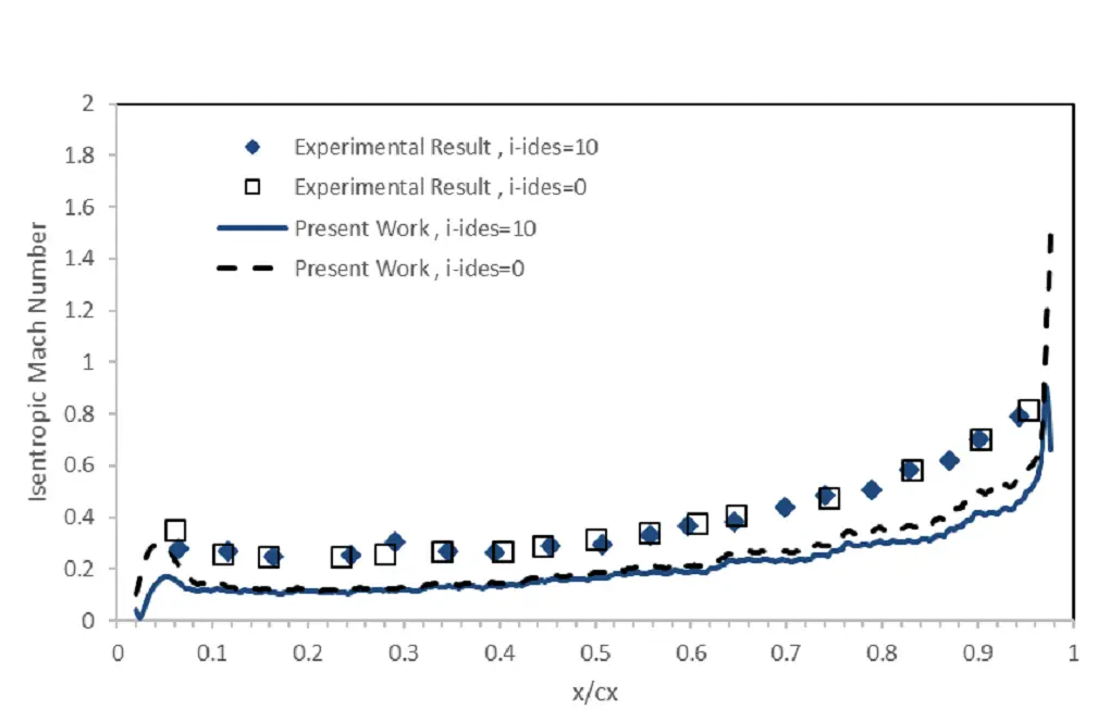
Table 1: Exit Mach number at different pressure ratio, design and off-design incidence
| i-ides | P2/Pt1 | P2 | M2 | |
| Experimental | 0 | 0.704 | - | 0.71 |
| Present Work | 0 | 0.704 | 35.2KPa | 0.678 |
| Experimental | 10 | 0.416 | - | 1.15 |
| Present Work | 10 | 0.416 | 20.8KPa | 1.106 |
| Experimental | 0 | 0.479 | - | 1.06 |
| Present Work | 0 | 0.479 | 23.95KPa | 1.014 |
| Experimental | 10 | 0.721 | - | 0.68 |
| Present Work | 10 | 0.721 | 36.05KPa | 0.633 |