Turbine Hydropower in Waterline Optimization, Paper Numerical Validation by ANSYS Fluent
Price: $240
In this project, we intend to simulate the lift-based in-pipe water turbine using the mesh motion method to compare and validate the results with the results in the article.
Turbine Hydropower in Waterline Optimization, Paper Numerical Validation by ANSYS Fluent
Price: $240
In this project, we intend to simulate the lift-based in-pipe water turbine using the mesh motion method to compare and validate the results with the results in the article.
Introduction
Using a spherical turbine based on lift-based in-pipe, this paper "Numerical analysis of lift-based in-pipe turbine for predicting hydropower harnessing potential in selected water distribution networks for waterlines optimization" model and simulates the possibility of operating a power plant inside a pipe. Turbine hydrofoil profiles are manufactured using NACA airfoils. For this purpose, the simulated model (CAD) of spherical lift turbine based on peak and bottom volume discharge rates has been simulated and analyzed in ANSYS Fluent software. The time series of power outputs is calculated from the time series of discharge changes.
The importance of saving water and energy has been one of the world's main concerns in recent years and is expected to become more important soon. In this regard, many technical ways have been proposed to replace pressure relief valves with power generators to generate electricity and safely regulate the pressure of water distribution networks. The energy efficiency of water supply systems is increased by using the hydraulic energy efficiency of water, which can be converted directly into electricity. Such a process uses a clean energy source, which is often neglected in water resources and reduces energy dependence on the power grid and system operating costs.
Paper Description
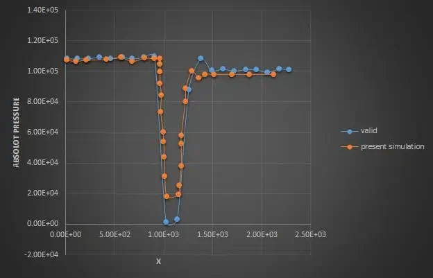
In this project, we intend to simulate the water turbine inside the pipe using the mesh motion method and compare the results with the results in the article. The mass flow is equal to 111 m^3/s, and the rotational speed is 153,626 rpm. The pressure diagram in the pipeline's centerline is compared with the paper diagram.
Turbine Geometry
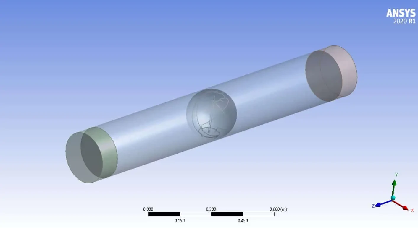
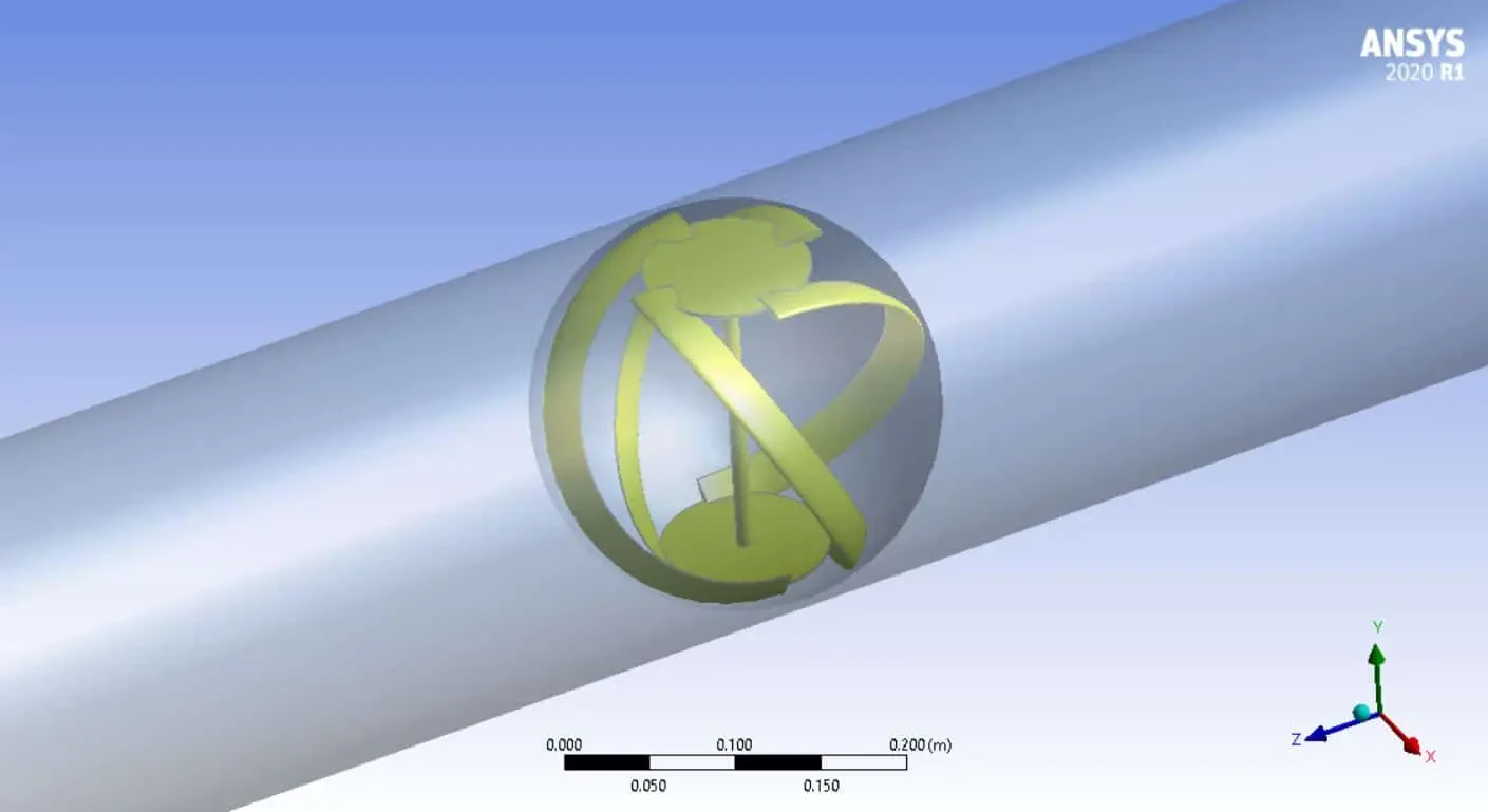
First, the geometry of the test chamber is designed in SolidWorks software , and the Design Modeler is prepared to create the grid. The geometry file is implemented in the Ansys meshing software to create the grid and name the boundary conditions.
Turbine Mesh
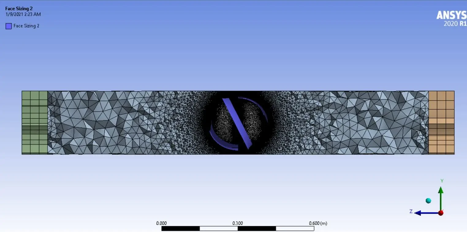
We carry out the model's meshing using ANSYS Meshing software.
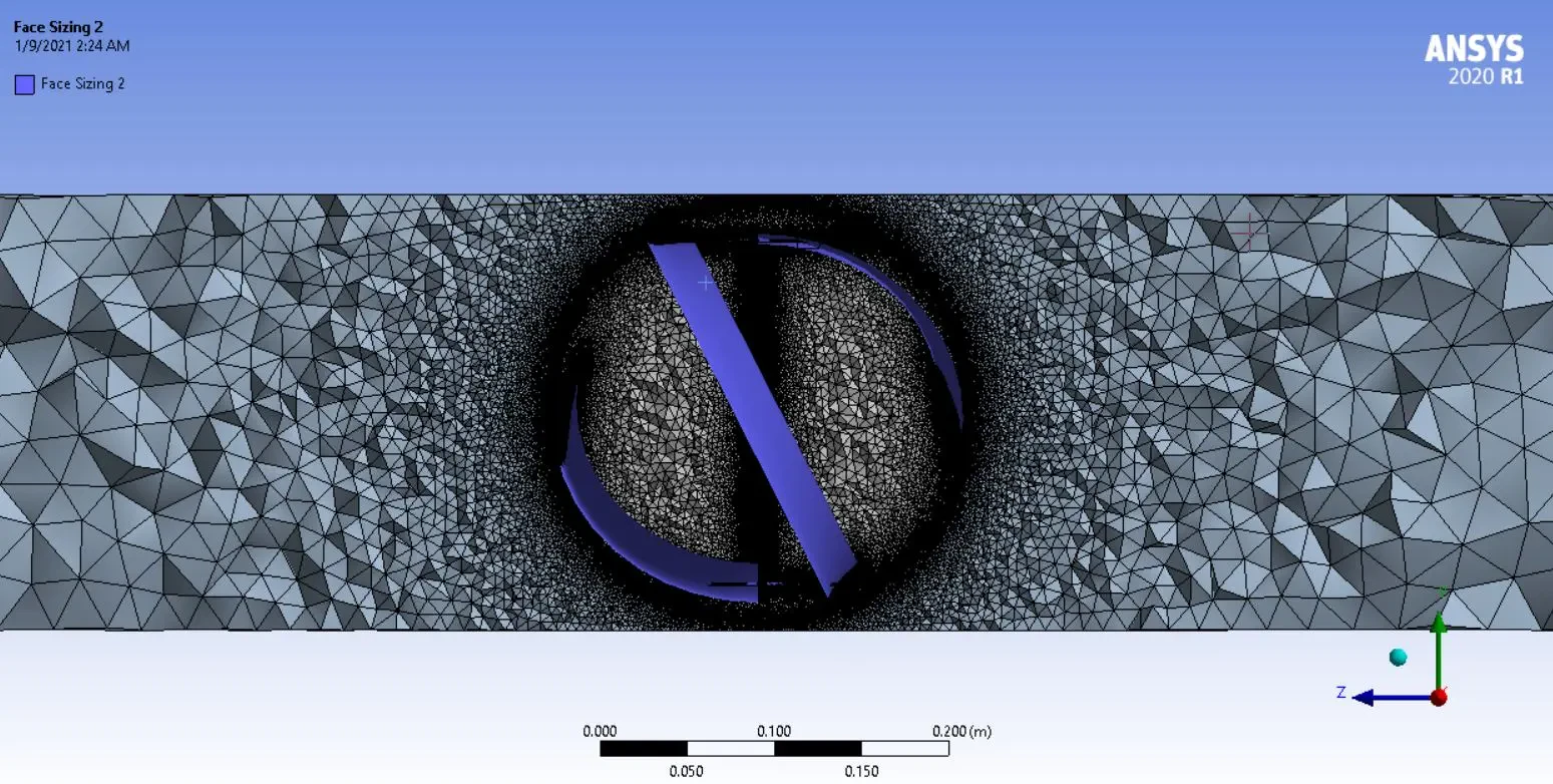
Grid Study
To check the mesh independence, it is necessary to lower the grid size so that our results are no longer affected by element number.
For this purpose, we first start from the element number of 250000, and by doubling the number of elements, we examine the output speed of the pipe as a factor for the mesh independence.
For a pipe with a length of 10 meters and a diameter of 0.3 meters and an inlet speed of 200 meters per second, and roughness of 0.03 mm, we check the mesh independence. The results are shown in the table below.
| case | mesh | P_in-P_out | error% |
| 1 | 250000 | 10851 | 0 |
| 2 | 500000 | 10420 | 4.1% |
| 3 | 1000000 | 10230 | 1.85% |
| 4 | 2000000 | 10221 | 0.01% |
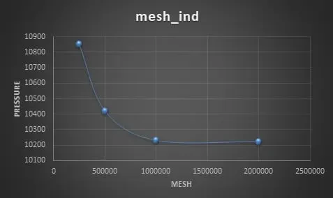
As can be seen in the figure and table above, the difference between the solution results is less than 1% with 2 million and 1 million elements. So the 1 million grids is the final element number for the main CFD simulation.
Turbine Boundary Condition & CFD Simulation
The boundary conditions are as follows: the inlet of the pipe as Velocity inlet, which is based on the flow (112 m3/h) and the output as pressure outlet, and the boundary condition of the turbine structure is defined as the wall in Fluent software.
To rotate the impeller in Fluent software, it is necessary to put a computational domain around it.
This domain, in this case, is considered a sphere. Using the rotational boundary condition (MESH motion), leads this spherical domain to rotate.
In this solution, the k-e Standard turbulence model (Standard wall Function) is used, and also, the simple algorithm is used for velocity and pressure coupling. The first-order method is used to discretize all parameters.
| Models | ||
| Viscous | k-epsilon | |
| k-epsilon model | standard | |
| Near wall treatment | Standard wall function | |
| Cell zone conditions | ||
| Fluid-r | Rotation zone axis z | 153.626 rpm |
| Fluid-s | ||
| Boundary conditions | ||
| Inlet | Velocity Inlet | |
| velocity magnitude | 0.63379 m/s | |
| Outlet | Pressure Outlet | |
| Pressure outlet | 0 pa | |
| Wall | Wall | |
| Wind-turbine | wall | |
| symmetry | ||
| side | - | |
| interface | ||
| stationary wall motion | Cylinder-s | |
| Rotary wall motion | Cylinder-r | |
| Methods | ||
| Pressure-Velocity Coupling | SIMPLE | |
| Pressure | PRESTO | |
| momentum | first order upwind | |
| turbulent kinetic energy | first order upwind | |
| specific dissipation rate | first order upwind | |
| gradient | Least squares cell base | |
| Initialization | ||
| Initialization methods | Standard | |
| gauge pressure | 0 pa | |
| velocity | 0.6337 m/s | |
| Material | ||
| Material properties | Standard | |
| density | 998.2 kg.m-3 | |
| viscosity | 0.001003 kg.m-1.s-1 | |
Results & Article Validation
The result of this study showed that the amount of fluid flow, effective head, pipe diameter, hydrofoil specifications, and turbine components determine the potential of hydropower utilization in each water distribution system.
The absolute pressure values obtained in the paper and the simulation results are shown in the figure below, which are very well matched.