Turgo Turbine, ANSYS Fluent CFD Simulation Training
Price: $24
- The present problem simulates the water flow inside a Turgo water turbine by ANSYS Fluent software.
- The geometry is designed using Design Modeler software.
- The meshing of the model has been done using ANSYS Meshing software and the element number is 4,344,106.
- Mesh Motion (Sliding Mesh) is used to define the rotation of the blades inside the chamber.
Description
The current project simulates a Turgo turbine using ANSYS Fluent software. The water flows at a velocity of 4 m.s-1 and passes the water turbine. Turgo Turbines are a type of impulse water turbine. They are highly efficient and compact, making them suitable for many hydroelectric applications, especially where high head conditions are present.
The Turgo turbine is distinct due to its unique design and operational principles. Unlike other turbines, it uses the kinetic energy of water, which is directed onto its blades to generate rotational motion. This motion is then converted into electrical energy, a process that is central to the functioning of hydroelectric power plants.
The blades are drawn in SOLIDWORKS software at a certain angle and distance from the central axis and then imported to the Design Modeler software for integrated blade design. In the space around the turgo turbine blades, a special cylinder is created to make a circulating water flow, and a rectangular cube space is designed as a space for free water flow.
The meshing was done using ANSYS Meshing software, and the mesh type is unstructured. To increase the meshing accuracy, the Method used is Tetrahedrons, and the element number is 4,344,106.
Turgo Turbine Methodology
The Mesh Motion (Sliding Mesh) technique is used to simulate the rotation of the turbine blades. Therefore, for the cylindrical region, the mesh mode is defined by defining a rotational speed of 150 rpm around the central horizontal axis of the turbine.
The realizable K-epsilon model is selected for turbulence characteristics of fluid flow, and the effects of gravity are considered in the Z direction with a value of -9.81 m/s2.
Conclusion
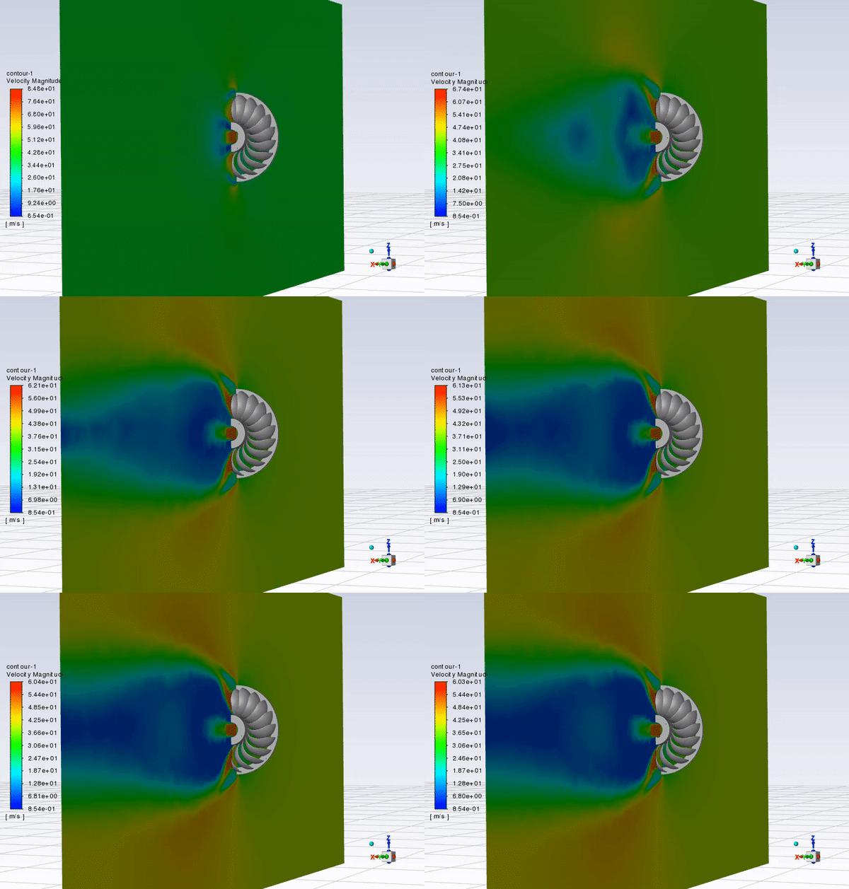
At the end of the solution process, two-dimensional and three-dimensional contours related to pressure, velocity, and velocity vectors are obtained. As it is obvious, the maximum velocity occurs near the rotating blades. Also, all the possible results can be extracted, like the pressure drop equal to 4.979 e+4.
Finally, the animation file shows the velocity of water, which hits the turbine blades and rotates them in the direction shown.