

Two Stream Combustion, CFD Simulation ANSYS Fluent Training
Price: $48
The present simulation is about two-stream combustion via ANSYS Fluent, and the results of this simulation have been analyzed.
Two Stream Combustion, CFD Simulation ANSYS Fluent Training
Price: $48
The present simulation is about two-stream combustion via ANSYS Fluent, and the results of this simulation have been analyzed.
Two Stream Combustion Description
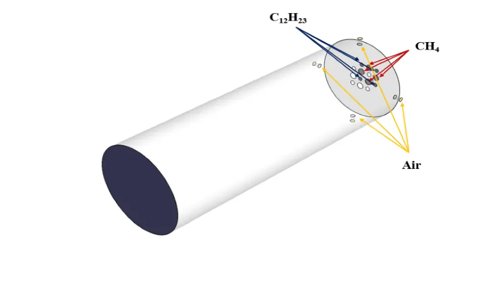
The present simulation is about two stream combustion via ANSYS Fluent. The combustion reaction occurs when air is combined with hydrocarbon fuel to convert fuel energy into heat energy. Sometimes two fuel streams are used to carry out the combustion reaction. The reaction by which two fuel streams react with an oxidizer is called two-stream combustion. In this project, a horizontal cylindrical combustion chamber is modeled. Methane (CH4) and diesel (C12H23) are used as fuel to combine with the oxidant to produce a combustion reaction. In this combustion chamber, four separate inlets are installed for each primary fuel, secondary fuel, and oxidizing stream. CH4 stream with a flow rate of 0.02 kg/s and a temperature of 810 K, C12H23 stream with a flow rate of 0.02 kg/s and a temperature of 530 K, and oxidizer with a flow rate of 1.2 kg/s and a temperature of 723 K enters the combustion chamber. The species model has been used to define the combustion reaction in this numerical simulation. The species model is also defined in a non-premixed combustion mode. In this type of combustion, fuel and oxidizer enter the reaction zone of the combustion chamber through separate paths; That is, they do not mix before entering the combustion chamber. In the non-premixed combustion model, the definition of a mixture fraction is used, which represents the mass fraction derived from the fuel stream. Also, since secondary fuel is used in this combustion chamber, the secondary stream must be activated.
Geometry & Mesh
The present geometry is designed in a 3D model via SpaceClaim software. The computational zone is the interior of a horizontal cylindrical combustion chamber. In the inlet section of this combustion chamber, four inlets for primary fuel, secondary fuel, and airflow are designed.
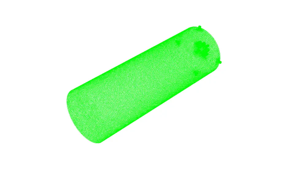
The mesh of the present model has been done via ANSYS Meshing. Mesh is done unstructured, and the number of production cells equals 689854.
Set-up & Solution
Assumptions used in this simulation :
- Pressure-based solver is used.
- The present simulation is steady.
- The effect of gravity on the model is ignored.
| Models | ||
| Viscous | k-epsilon | |
| k-epsilon model | realizable | |
| near-wall treatment | standard wall function | |
| Species | Non-Premixed | |
| energy treatment | non-adiabatic | |
| stream option | secondary stream | |
| fuel temperature | 810 K | |
| oxide temperature | 723 K | |
| second temperature | 530 K | |
| species | fuel : 1CH4 oxide : 0.79N2 & 0.21 O2 second : 1C12H23 | |
| Energy | On | |
| Boundary conditions | ||
| Inlet-Fuel | Mass Flow Inlet | |
| mass flow rate | 0.02 kg.s-1 | |
| temperature | 810 K | |
| mean mixture fraction | 1 | |
| Inlet-Oxid | Mass Flow Inlet | |
| mass flow rate | 1.2 kg.s-1 | |
| temperature | 723 K | |
| mean mixture fraction | 0 | |
| Inlet-Secondary | Mass Flow Inlet | |
| mass flow rate | 0.02 kg.s-1 | |
| temperature | 530 K | |
| secondary mean mixture fraction | 1 | |
| Outlet | Pressure Outlet | |
| gauge pressure | 0 Pascal | |
| Wall | Wall | |
| wall motion | stationary wall | |
| heat flux | 0 W.m-2 | |
| Methods | ||
| Pressure-Velocity Coupling | SIMPLE | |
| pressure | standard | |
| momentum | first-order upwind | |
| turbulent kinetic energy | first-order upwind | |
| turbulent dissipation rate | first-order upwind | |
| mean mixture fraction | first-order upwind | |
| mean mixture variance | first-order upwind | |
| secondary mean mixture fraction | first-order upwind | |
| secondary mean mixture variance | first-order upwind | |
| energy | first-order upwind | |
| Initialization | ||
| Initialization methods | Hybrid | |
Two Stream Combustion Results
After calculation, 2D and 3D contours related to pressure, velocity, temperature, and species’ mass fraction ( CH4, CO2, C12H23, O2, H2O, H2, CO ), water-liquid volume fraction, and water-vapor volume fraction are obtained. The results show that the temperature in the reaction zone increases significantly. In other words, where the primary and secondary fuel streams and the oxidizing stream inside the combustion chamber combine, the combustion reaction occurs. As a result, high thermal energy is produced. Also, at the beginning of the combustion chamber, the mass fraction of each reactant (including CH4, C12H23, and O2) decreases, and then the amount of each of the reaction products (such as CO2, CO, H2O, etc. ) increases. This indicates that the combustion reaction is taking place correctly and that as a result of this reaction, fuel and oxidizing streams are converted into reaction products.