

Underfloor Heating System CFD Simulation, ANSYS Fluent Training
Price: $80
In this project, the heat transfer of an underfloor heating system in an enclosed space is simulated and analyzed.
Underfloor Heating System CFD Simulation, ANSYS Fluent Training
Price: $80
In this project, the heat transfer of an underfloor heating system in an enclosed space is simulated and analyzed.

Introduction
Air conditioning is one of the most important branches of mechanical engineering. Regulating the temperature of a room or a building has always been one of the major concerns of air conditioning designers. The high cost of energy consumption required to provide conditioned air for each structure by its use has led to the design of the best air conditioning system for each structure. These designs require a lot of study and research, both in terms of construction and maintenance costs and in terms of best performance. Meanwhile, simulation and analysis of these systems can play an effective role in determining the most appropriate ventilation system for each structure.
Project description
In this project, the heat transfer of an underfloor heating system in an enclosed space was simulated and analyzed by ANSYS Fluent. it is assumed that the underfloor heating system generated heat flux is assigned to the bottom wall (other walls are considered to be adiabatic). Since in this analysis, an underfloor heating system is used to generate heat, no fluid flow inlet is used in this project and only a pressure outlet is defined. The heat transfer is of the free convection type and gravity acceleration must be considered. The energy and k-epsilon Realizable models are used to solve the energy equation, and fluid flow parameters and to thoroughly analyze the effects of buoyancy and volumetric forces resulting from density changes. It should be noted that the ideal gas model has been used to determine the density changes in proportion to temperature.
Geometry and mesh
The geometry required for this project consists of a room that is Designed in Ansys Design Modeler software and meshed by Ansys Meshing. The mesh type used for this geometry is unstructured and the element number is 124325.
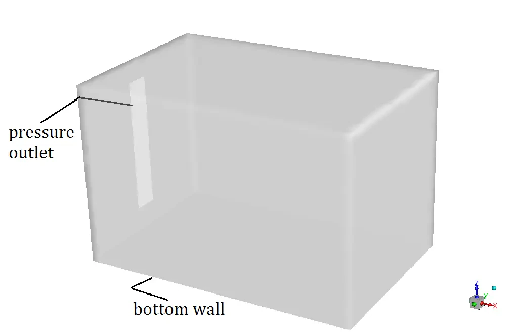
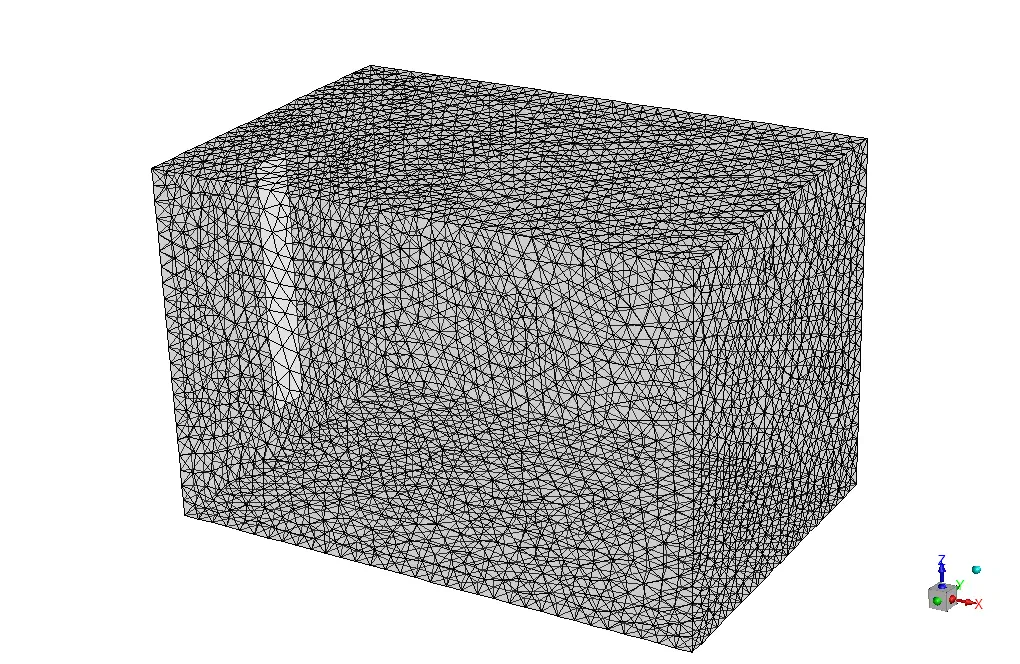
Underfloor Heating System CFD Simulation
The key assumptions considered in this project are:
- Simulation is done using a pressure-based solver.
- The present simulation and its results are considered to be steady and do not change as a function of time.
- The effect of gravity has been taken into account and is equal to -9.81 m/s2 in the Z direction.
The applied settings are summarized in the following table.
| Models | ||
| Viscous model | k-epsilon | |
| k-epsilon model | realizable | |
| near wall treatment | standard wall function | |
| Energy | on | |
| (underfloor heating system) | Boundary conditions | |
| Outlet | Pressure outlet | |
| Gauge pressure | 0 Pa | |
| Turbulent intensity | 5 % | |
| Turbulent viscosity ratio | 10 | |
| Temperature | 300 K | |
| Walls | ||
| bottom wall | wall motion | stationary wall |
| Heat flux | 180 W/m2 | |
| Top and sidewalls | wall motion | stationary wall |
| Heat flux | 0 W/m2 | |
| (underfloor heating system) | Solution Methods | |
| Pressure-velocity coupling | coupled | |
| Spatial discretization | Pressure | second order |
| Density | second order upwind | |
| Momentum | second order upwind | |
| Energy | second order upwind | |
| turbulent kinetic energy | first order upwind | |
| turbulent dissipation rate | first order upwind | |
| (underfloor heating system) | Initialization | |
| Initialization method | Standard | |
| gauge pressure | 0 Pa | |
| Velocity (x,y,z) | (0,0,0) m/s | |
| temperature | 300 K | |
| Turbulent kinetic energy | 1 m2/s2 | |
| Turbulent dissipation rate | 1 m2/s3 | |
Underfloor Heating System Results
Contours of pressure, velocity, temperature, etc. are obtained and presented in both 3D and 2D.