

Vertical Heat Exchanger, ANSYS Fluent CFD Simulation
Price: $8
The present problem simulates heat transfer in a three-dimensional vertical heat exchanger using ANSYS Fluent software.
Vertical Heat Exchanger, ANSYS Fluent CFD Simulation
Price: $8
The present problem simulates heat transfer in a three-dimensional vertical heat exchanger using ANSYS Fluent software.
Vertical Heat Exchanger, ANSYS Fluent CFD Simulation Training
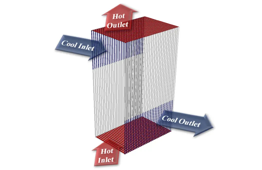
The present problem simulates heat transfer in a three-dimensional vertical heat exchanger using ANSYS Fluent software. This heat exchanger is designed vertically; In this way, the flow of cold fluid enters from the upper part of one of the sidewalls of the heat exchanger and exits from the lower portion of the sidewall in front of it; While the flow of hot fluid from the floor of the heat exchanger enters vertically and upwards and exits the ceiling. Cold fluid flow enters the heat exchanger at a velocity of 8.88 ms-1 and temperature of 239.15 K through 30 vents. Hot fluid flow enters the heat exchanger at a velocity of 15.23 ms-1 and temperature of 393.15 K through 30 vents.
The hot fluid defined in the model has a density of 0.898 kg.m-3, a specific heat capacity of 1013 j.kg-1.K-1, a thermal conductivity of 0.0238 Wm-1.K-1, and a viscosity of 1.7894 e-5. The cold fluid defined in the model has a density equal to 1.205 kg.m-3, specific heat capacity equal to 1005 j.kg-1.K-1, thermal conductivity equal to 0.0257 Wm-1.K- 1, and the viscosity is equal to 1.7894e-5. Also, all the inner walls of the heat exchanger and the outer wall of the heat exchanger are made of aluminum, and the external body of the heat exchanger has a thermal insulation boundary condition.
Geometry & Mesh
The present model is designed in three dimensions using Design Modeler software. The model is related to a heat exchanger in the shape of a vertical rectangular cube with a rectangular cross-section with a length and width of 1 m and 1.5 m and 3 m. The cold flow inlet of the heat exchanger is in the upper part of one of its sidewalls, which consists of 30 narrow holes, and the hot flow inlet is located on the floor of the heat exchanger, which has 30 tiny holes. Each cold flow inlet has a width of 0.015 m and a length of 1 m; While each of the hot flow inlet vents has a width of 0.035 m and a length of 1 m. The cold flow outlet is in the lower part of the sidewall in front of its inlet, and the hot flow outlet is located on the roof of the heat exchanger.
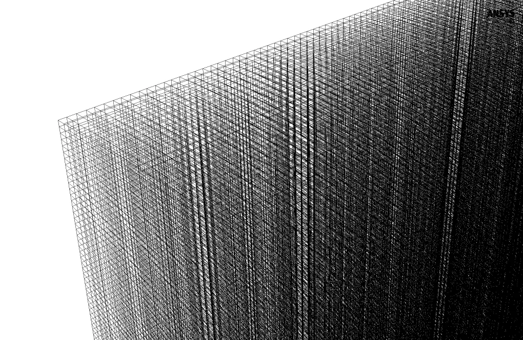
We carry out the model's meshing using ANSYS Meshing software, and the mesh type is unstructured. The element number is 939600. The following figure shows the mesh.
CFD Simulation
We consider several assumptions to simulate the present model:
- We perform a pressure-based solver.
- The simulation is steady.
- The gravity effect on the fluid is ignored.
The following table represents a summary of the defining steps of the problem and its solution:
| Models | ||
| Viscous | k-epsilon | |
| k-epsilon model | standard | |
| near wall treatment | standard wall functions | |
| Energy | On | |
| Boundary conditions | ||
| Inlet - Cool | Velocity Inlet | |
| velocity magnitude | 8.88 m.s-1 | |
| temperature | 293.15 K | |
| Inlet - Ho | Velocity Inlet | |
| velocity magnitude | 15.23 m.s-1 | |
| temperature | 393.15 K | |
| Outlet - Cool & Hot | Pressure Outlet | |
| gauge pressure | 0 pascal | |
| Inner Wall | Wall | |
| wall motion | stationary wall | |
| thermal condition | coupled | |
| wall thickness | 0.002 m | |
| Outer Wall | Wall | |
| wall motion | stationary wall | |
| heat flux | 0 W.m-2 | |
| Methods | ||
| Pressure-Velocity Coupling | SIMPLE | |
| Pressure | second order | |
| momentum | second order upwind | |
| turbulent kinetic energy | first order upwind | |
| turbulent dissipation rate | first order upwind | |
| energy | second order upwind | |
| Initialization | ||
| Initialization methods | Hybrid | |
Results & Discussions
At the end of the solving process, two-dimensional and three-dimensional contours related to pressure, speed, and temperature are obtained. The results show that the heat transfer is allowed so that the cold part of the heat exchanger increases the temperature and the hot part of the heat exchanger decreases the temperature.